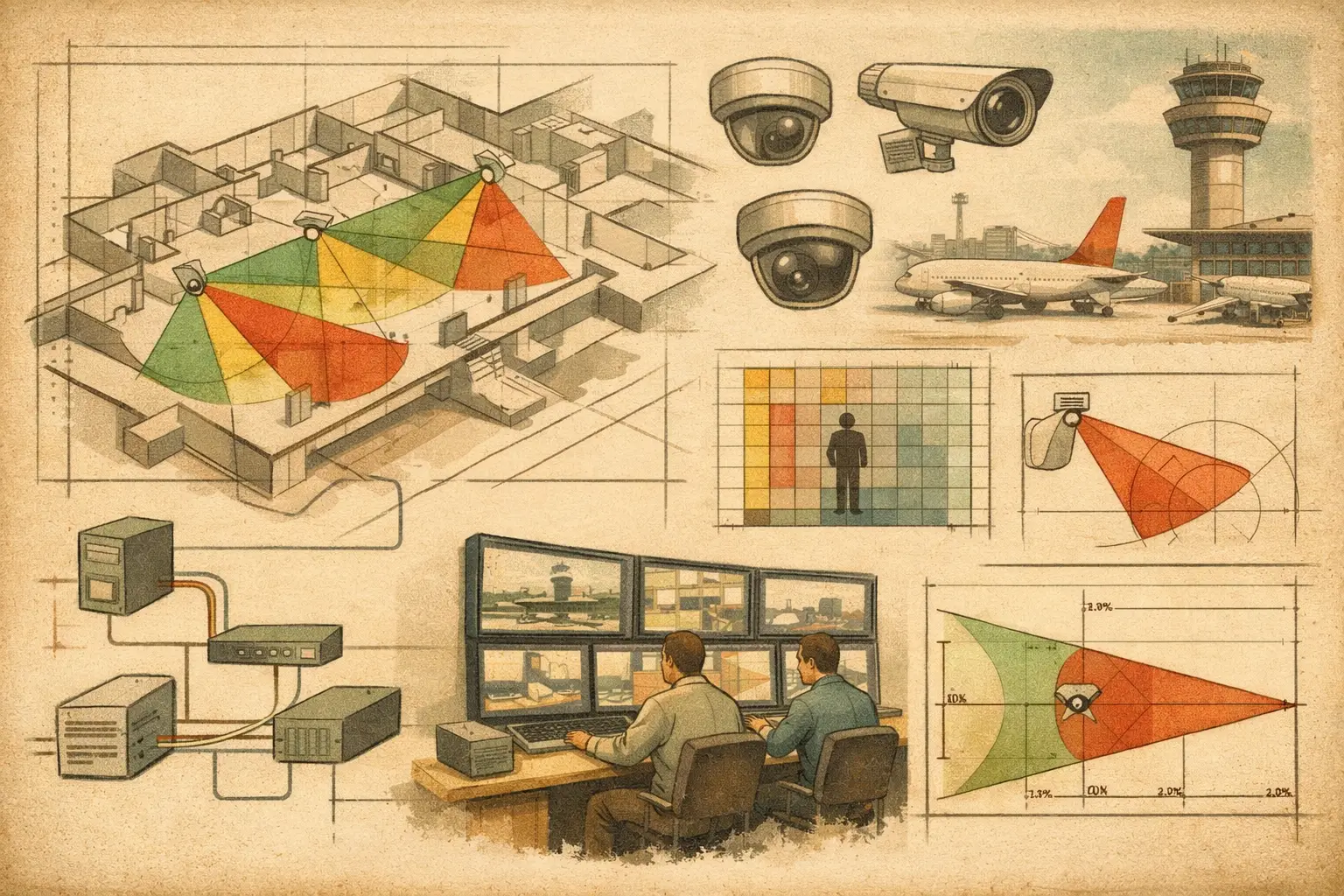
A missed view at an airport is rarely caused by a lack of cameras alone. It is more often the result of a camera that was positioned without the right focal length, a coverage cone that ignored a structural obstruction, or a network route that was not coordinated until installation. This airport camera planning guide sets out a disciplined design workflow for translating operational requirements into verifiable camera coverage and technical documentation.
Airport projects add layers of complexity that are less common in standard commercial CCTV design. Terminals combine public circulation, restricted areas, retail units, baggage handling, curbside traffic, aircraft-side operations, and security-controlled doors. Each space has different observation objectives, lighting conditions, mounting constraints, privacy considerations, and stakeholder requirements. A workable design must make these differences visible rather than treating the airport as one large floor plan.
Start With Operational Zones, Not Camera Symbols
The first design decision is to divide the site into operational zones and assign a surveillance purpose to each. A landside arrivals hall may require broad situational awareness and queue monitoring. A boarding gate may require recognition-level coverage at access points. A baggage make-up area may need observation of operational activity, while a sterile corridor may require more deliberate coverage of movement through controlled boundaries.
This distinction matters because the same camera type and lens setting cannot satisfy every task. A wide field of view can show general activity over a large area, but it spreads the available pixels across that area. A narrower field of view may support higher pixel density at a doorway, counter, or screening approach, but it covers less surrounding context.
Before placing cameras, create a zone schedule that records the area name, operational purpose, target subjects, required observation task, key constraints, and responsible stakeholder. This becomes the design brief against which every camera location can be reviewed. It also prevents later disagreements caused by vague terms such as “cover the terminal” or “monitor the entrance.”
Import and Calibrate the Airport Drawing
A camera layout is only as dependable as its underlying geometry. Import the latest architectural, fit-out, or coordinated security drawing, then calibrate its scale using a known dimension. A scale calibration error affects every subsequent result: camera distance, field of view width, pixel density, mounting height interpretation, and cable-route estimate.
Airport drawings often contain multiple revisions, tenant changes, phased construction boundaries, and areas withheld from general circulation. Record the drawing title, revision, date, and scale reference used for the design. If a plan is not verified, treat calculated distances as provisional and flag the dependency in the report.
Next, review walls, glazed partitions, counters, baggage conveyors, security lanes, columns, signage, and soffits. These are not drafting details. They are physical geometry that can create occlusion. A camera cone drawn through a wall, a solid retail fascia, or a baggage screening machine does not represent usable coverage.
Model Heights and Obstructions in Three Dimensions
Two-dimensional planning is useful for camera direction and horizontal coverage, but airports demand a three-dimensional review. Mounting height, camera tilt, target height, and the elevation of obstructions all change what the camera can see.
For example, a camera mounted high in an arrivals hall may clear a queue barrier but lose useful facial detail because of its steep angle. A lower camera may improve the viewing angle at a controlled door, yet be more vulnerable to tampering or blocked by passengers. Neither option is automatically correct. The design must compare the operational need with the physical constraints.
Include likely temporary obstructions where project information permits. Check-in queues, advertising displays, seasonal wayfinding, and mobile equipment can all alter sightlines. Permanent geometry can be modeled directly; operational changes should be identified as assumptions requiring site validation.
Select Camera Parameters From the Required Result
Camera placement should follow the required image detail, not the other way around. Define whether each scene needs detection, observation, recognition, or identification capability, then review pixel density or PPM at the relevant target distance. DORI is a helpful common framework for communicating these requirements, provided the project team agrees on how it will be applied.
Resolution alone does not determine performance. Sensor size, focal length, mounting distance, scene width, camera tilt, compression settings, lighting, motion, and manufacturer image processing all influence real-world footage. A calculated PPM value is a design input and review output, not a guarantee of evidential performance in every condition.
For each camera, document at least the resolution, sensor size, focal length or varifocal range, mounting height, direction, tilt, and intended coverage objective. With these inputs, a designer can calculate the horizontal field of view and evaluate pixel density at critical locations rather than relying on approximate cones.
Use Fixed and Varifocal Lenses Deliberately
Fixed-lens cameras are useful where the scene geometry is stable and repeatability matters. They can simplify the schedule and reduce the chance of field adjustments changing an approved coverage plan. Varifocal cameras offer flexibility where final mounting positions, tenant fit-out, or target distances are uncertain.
That flexibility comes with a control requirement. If the final focal length is adjusted on site, the installed field of view may no longer match the design drawing. Capture the final lens setting, direction, and tilt during commissioning so that the as-built record remains traceable.
Plan Overlap Without Creating Wasteful Duplication
Coverage overlap is valuable at entrances, security thresholds, concourse junctions, and handover points between camera views. It supports continuity when a subject moves from one scene to another and can provide a secondary angle where one camera is affected by glare, crowding, or occlusion.
However, overlap should be intentional. Excessive duplication can consume camera channels, storage capacity, switch ports, and review time without improving the required operational outcome. Review overlaps against a stated reason: continuity, alternate angle, critical asset protection, or resilience at a controlled boundary.
Blind spots should be assessed in the same disciplined way. Some blind areas are acceptable because they fall outside the surveillance objective or cannot be addressed without impractical infrastructure. Others are material risks, such as an unobserved approach to a secure door. Mark both conditions clearly so reviewers can distinguish accepted limitations from unresolved design gaps.
Coordinate Network Topology Early
An airport camera plan is also a network planning exercise. Camera locations influence cable pathways, telecommunications room loading, PoE switch capacity, fiber backbone requirements, cabinet space, and maintenance access. Deferring these checks until after camera placement creates avoidable revisions.
Group cameras by operational area and likely network distribution point. Record estimated bandwidth, power demand, cable type, pathway assumptions, and any need for local aggregation. High-resolution cameras, higher frame rates, analytics, and long retention requirements can materially affect network and storage calculations, but values should be based on the selected system configuration and verified manufacturer documentation.
Coordinate with ICT, electrical, architectural, and aviation operations teams before finalizing routes or mounting locations. A suitable camera position may still be unsuitable if it conflicts with fire-rated construction, access panels, signage, passenger wayfinding, or maintenance restrictions.
Produce a Reviewable Airport Camera Planning Package
The final deliverable should allow another qualified professional to understand why each camera exists and what it is expected to achieve. A professional package normally includes calibrated plans, camera identifiers, fields of view, DORI or PPM review results, mounting details, blind-spot notes, overlap rationale, camera schedules, network assumptions, and a record of open items.
CCTV Design Tool Online can support this workflow in one persistent workspace by combining calibrated drawings, physical geometry, camera parameters, coverage visualization, pixel-density review, network planning, and structured reporting. The output remains a design record, not a substitute for site verification, manufacturer confirmation, or jurisdiction-specific review.
Before issue, conduct a final coordination review with the question that matters most: can each stakeholder trace every critical camera from its operational objective to its physical position, calculated coverage, infrastructure dependency, and documented limitation? When that traceability is present, the design is far easier to install, review, revise, and maintain through the airport’s changing operational life.