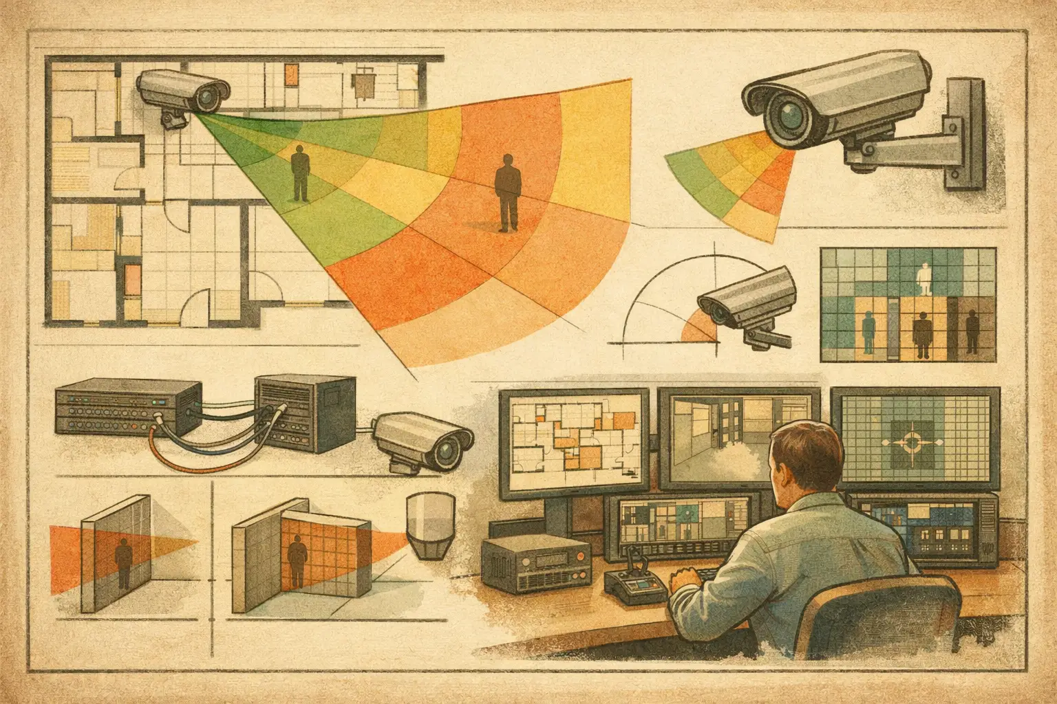
A camera cone drawn on a floor plan is only useful when its dimensions come from real optical and physical inputs. To calculate camera field of view reliably, security designers need more than a viewing-angle figure from a datasheet. They need the camera's active sensor dimensions, focal length, working distance, mounting geometry, image resolution, and the operational detail required at the target area.
The calculation establishes a design result, not a guarantee of installed performance. Final image quality can still be affected by lens tolerances, focus, lighting, compression, scene contrast, motion, weather, and obstructions that are not represented in the drawing. Used correctly, field-of-view calculations provide a traceable starting point for camera selection, placement, DORI review, and coordination with architecture and network design.
How to Calculate Camera Field of View
Camera field of view is commonly described in two related ways: angular field of view and scene coverage at a given distance. The angular value tells you how wide the lens sees. The scene coverage tells you the real-world width or height visible at the target plane. For CCTV design, the second value is usually more actionable because it connects optics to a door, lane, gate, corridor, perimeter line, or other monitored area.
For a rectilinear lens, calculate the horizontal angle of view with:
`Horizontal FoV = 2 × arctan(sensor width ÷ (2 × focal length))`
Use the sensor's active horizontal dimension and the focal length in the same unit, usually millimeters. The equivalent vertical calculation uses sensor height. Once the angle is known, calculate the visible scene width at a distance:
`Scene width = 2 × distance × tan(horizontal FoV ÷ 2)`
Distance must be measured from the camera to the target plane, not simply from the camera to an arbitrary point on the plan. In a corridor, that may be the end of the required observation zone. At an entrance, it may be the face-position or identification plane. On a perimeter, it may be the fence line or a defined detection boundary.
A practical calculation example
Assume a camera has a 1/2.8-inch format sensor with an active width of 5.6 mm and a fixed 4 mm lens. The horizontal angle is approximately:
`2 × arctan(5.6 ÷ 8) = about 70 degrees`
At a target plane 10 m from the camera, the scene width is approximately:
`2 × 10 × tan(35 degrees) = about 14 m`
If the camera records 3840 horizontal pixels, the theoretical pixel density across that 14 m width is approximately 274 pixels per meter, or 83 PPM. This is a calculated value before compression, focus accuracy, low-light behavior, motion blur, and image processing are considered.
This example also shows why resolution alone does not define usable coverage. The same 4K camera may provide substantially different PPM depending on the selected focal length and the distance to the target. A wider lens covers more area but spreads the same pixel count across a wider scene.
Start With Verified Camera Inputs
The field-of-view calculation is only as dependable as its inputs. Obtain focal length, sensor format or active sensor dimensions, and resolution from the manufacturer datasheet for the exact camera and lens configuration. Do not assume that two cameras described as having the same sensor format have identical active imaging dimensions.
For a varifocal camera, calculate coverage at the intended focal setting rather than at the minimum or maximum lens specification. A lens listed as 2.8-12 mm does not have one field of view. It has a range, and the final setting may change during commissioning if the original design intent is not documented clearly.
Where manufacturer-provided angle-of-view values are available for the selected camera-lens combination, compare them with the calculated result. Small differences can arise from active sensor area, lens design, distortion correction, rounding, or published specifications. The manufacturer data should guide the final camera schedule, while the geometric calculation remains valuable for validating plan coverage.
Convert Optical Coverage Into a CCTV Design Decision
A calculated field of view becomes useful when it is tested against the required surveillance outcome. Ask what the camera must achieve at the farthest relevant point: general monitoring, detection, observation, recognition, or identification. DORI provides a common way to frame that discussion, but project teams should confirm the required pixel-density criteria and acceptance method for the specific application.
PPM is calculated by dividing image pixels across the relevant image dimension by the physical scene size in that direction. For horizontal coverage:
`PPM = horizontal image pixels ÷ scene width in meters`
The resulting PPM should be evaluated at the target plane, not only at the center of the camera view. A person moving through the outer edge of a wide-angle image may occupy fewer useful pixels than a person closer to the center. Lens distortion, perspective, and the camera's tilt can further affect the practical detail available across the scene.
This creates a recurring trade-off. A wide field of view can reduce camera quantity and improve general situational awareness, but it may leave insufficient pixel density for a narrow recognition or identification zone. A longer focal length can improve detail at distance, but it reduces contextual coverage and can create blind spots closer to the camera. Good design separates these objectives instead of expecting one camera to satisfy every operational requirement.
Account for Mounting Height, Tilt, and Perspective
A two-dimensional plan calculation can show horizontal coverage, but camera mounting geometry determines what the camera sees vertically. Mounting height, tilt angle, and target elevation affect the near-field blind spot, the far-field coverage, and the angle at which people or vehicle plates are viewed.
A camera mounted high above a lobby may appear to cover the entire floor area when viewed from above. Yet, if the camera is tilted steeply downward, faces near the outer edge may be seen at an unfavorable angle. Conversely, a shallow tilt may preserve a better view toward an entrance but leave space directly below the camera unobserved.
For exterior cameras, evaluate the target plane in three dimensions. A gate, roadway, fence line, retaining wall, loading dock, or vehicle lane may sit at a different elevation from the camera. A scene width based on flat horizontal distance can be misleading where slopes, ramps, or level changes are present.
Check Geometry Before Accepting the Coverage Cone
A field-of-view calculation describes an unobstructed optical cone. Real sites contain walls, glazing, columns, doors, shelving, signage, landscaping, parked vehicles, and other sources of occlusion. The camera may have enough theoretical coverage to see a corridor intersection, for example, while a wall return blocks the actual line of sight.
Import and calibrate the drawing before placing cameras. Scale calibration is fundamental: an incorrectly scaled plan produces incorrect distances, scene widths, PPM values, and mounting coordinates. Then review walls and physical geometry, including openings that may be represented differently from solid partitions.
Coverage should be inspected from both plan and camera perspectives. The plan view helps identify overlap, blind spots, and camera spacing. The camera view helps assess whether the visible geometry supports the intended DORI outcome. If an important target zone is obscured, moving the camera a short distance, changing its direction, or specifying a different focal length may be more effective than increasing resolution.
Use a Repeatable Field-of-View Workflow
For projects with multiple camera types and repeated revisions, a disciplined workflow prevents optical assumptions from being lost between design, installation, and review. Define the monitored target and required outcome first. Select a provisional camera using verified sensor, resolution, and lens data. Calculate its horizontal and vertical coverage at the required target distances, then review PPM and DORI across the specific zone.
Next, position the camera against calibrated physical geometry and test the line of sight for occlusion. Review mounting height and tilt, identify near-field blind spots, and confirm that intended overlap with adjacent cameras is purposeful rather than accidental. Finally, record the selected focal setting, orientation, mounting details, and coverage rationale in the camera schedule and technical report.
A browser-based workspace such as CCTV Design Tool Online can bring these steps together by connecting calibrated plans, camera specifications, field-of-view visualization, DORI and pixel-density analysis, wall geometry, and structured documentation. The value is not merely a camera cone on a drawing. It is the ability to revisit the assumptions behind that cone when the plan, camera model, ceiling layout, or operational requirement changes.
The best field-of-view calculation is one that remains understandable months later. When a reviewer can see the sensor input, focal setting, target distance, PPM result, mounting geometry, and visible obstructions, the design is easier to coordinate, revise, and verify during commissioning.