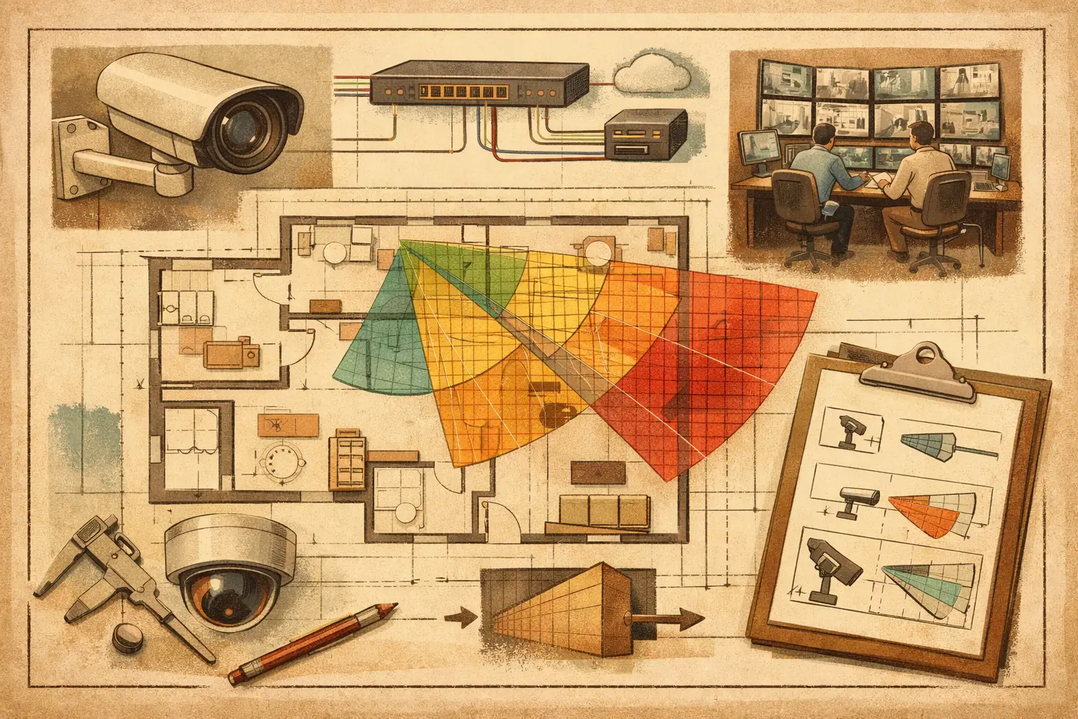
A camera cone drawn on an unscaled architectural PDF can look convincing while representing the wrong distance, field of view, and pixel density. To calibrate floor plan for CCTV design is therefore not an administrative step before camera placement. It is the measurement control that makes later coverage, DORI, mounting, and network decisions meaningful.
A small scale error can propagate through the entire design. A corridor that is modeled 10% too short may suggest that a wide-angle camera delivers identification-level pixel density at a doorway when the calculated result at the actual distance is materially lower. The same issue affects cable-route estimates, camera spacing, storage assumptions based on scene activity, and the clarity of the final technical report.
What Floor Plan Calibration Establishes
Scale calibration assigns real-world dimensions to a drawing. In practical terms, it tells the design workspace how many pixels, drawing units, or imported CAD units represent one foot or meter. Once that relationship is established, physical geometry can be modeled at a usable scale and camera calculations can refer to real distances.
Calibration does not make an old drawing correct. It only scales the drawing according to the reference information provided. If walls were moved during construction, an as-built survey conflicts with the issue drawing, or a scanned plan is distorted, the resulting CCTV model still needs review against verified site conditions.
For a security designer, the key outputs of calibration are straightforward: measured distances on the plan, camera-to-target distances, room and corridor dimensions, field-of-view extents, and pixel-density calculations expressed at known locations. These outputs support an engineering review; they are not a substitute for qualified site verification or jurisdiction-specific approval requirements.
Choose a Reference Dimension You Can Trust
The best calibration reference is a dimension that is both clearly labeled and unlikely to change. A dimensioned exterior wall, structural grid spacing, or a surveyed internal distance can be suitable. Door widths and furniture layouts are generally weaker references because they may be nominal, inconsistent between drawing sets, or altered during fit-out.
Use a reference that spans as much of the drawing as practical. A 30-foot structural-grid dimension normally produces less sensitivity to selection error than a 3-foot door opening. This matters especially when calibrating a raster image, where the operator must click the two endpoints manually.
Before setting the scale, confirm four details:
- The drawing revision is appropriate for the CCTV design stage.
- The reference dimension is stated in a known unit, such as feet, inches, or meters.
- Both endpoints are visible and unambiguous.
- The reference sits on the same plan area and level being modeled.
If the document is a PDF exported from CAD, check whether it contains vector geometry or has been scanned as an image. A vector PDF may preserve dimensions more consistently, while a scan can introduce stretching, rotation, and edge distortion. Neither format should be assumed to be correctly scaled just because the sheet includes a graphical scale bar.
Import and Calibrate the Drawing
Start with the cleanest available floor plan. Remove presentation layers that obscure walls, dimensions, and room names where possible. For multi-page drawing sets, import each level as a separate workspace or drawing layer rather than forcing multiple floors into one coordinate plane.
Select two exact points that match the endpoints of the chosen reference dimension. Enter the stated real-world value and unit. The design tool can then establish the scale relationship for the plan.
The selection points deserve more care than they usually receive. Choose wall faces, structural-grid intersections, or dimension extension-line origins, not the center of thick linework or a nearby annotation. On drawings with heavy plotting weights, a few pixels of error can represent several inches or more in the modeled environment.
After calibration, measure at least two additional known dimensions in different areas of the plan. For example, validate an office width near the calibration line and a corridor length farther away. If both values align within the accuracy appropriate to the project stage, the drawing is ready for geometry review. If the mismatch grows farther from the reference, investigate distortion rather than repeatedly adjusting the scale.
Use one unit system throughout the model
A design may originate in metric architectural drawings while equipment schedules, mounting details, or client requirements use imperial units. Either system can work, but the working model should use one consistent base unit. Mixed units create avoidable errors when entering mounting height, lens focal length, target distances, or network cable lengths.
If a project team must report in both units, convert deliberately in the deliverable. Do not calibrate a dimension labeled 12 meters as 12 feet and expect later camera calculations to reveal the mistake.
Check Geometry Before Positioning Cameras
A calibrated image is not yet a CCTV model. Walls, partitions, glazing, doors, shelving, and other physical features determine whether a calculated field of view is actually usable. The next task is to review or create the geometry that will affect sight lines.
External walls and permanent internal partitions should normally be modeled first. Then add the conditions most likely to create occlusion: secure-room partitions, elevator cores, warehouse racking, tall counters, and fixed equipment. A camera may have an unobstructed geometric angle to a target on the drawing but lose effective visibility behind a full-height partition or a high storage run.
Openings require similar care. A doorway can preserve a useful view through a wall, but its clear opening, leaf position, access-control hardware, and normal operating condition may change what the camera sees. Glazing is also not automatically transparent for every operational purpose. Reflection, tint, lighting contrast, and camera placement can reduce practical image quality even where the plan shows a direct line of sight.
This is where design intent and field performance should remain distinct. The model can calculate a field of view and identify geometry-based occlusion. Actual image performance depends on installed camera settings, lighting, scene contrast, compression, environmental conditions, and manufacturer-specific behavior.
Calibrate Floor Plans for CCTV Coverage Analysis
Once scale and geometry are credible, camera placement becomes a measurable exercise rather than a visual approximation. Position the camera using its intended mounting height, direction, tilt, sensor size, resolution, and focal length. Then review the resulting field of view against the operational target.
Pixel density is particularly dependent on calibrated distance. PPM, or pixels per foot, changes across the scene as distance increases. DORI planning uses pixel-density thresholds to assess whether an area may support detection, observation, recognition, or identification objectives. The relevant threshold should be defined by the project brief, client risk assessment, and applicable design criteria rather than assumed from a generic camera symbol.
A wide-angle camera may provide useful situational awareness across a lobby while providing insufficient pixel density at a distant reception desk. A narrower focal length can improve detail at the desk but may create blind spots around adjacent entrances. Calibration allows the team to see this trade-off in the proper physical context and decide whether a second camera, a changed mounting position, or a revised operational requirement is appropriate.
Review overlap where continuity matters, such as entrances, cash-handling areas, loading routes, and transitions between indoor and outdoor spaces. Overlap is not automatically beneficial everywhere. Excessive overlap can add cost, network load, and review complexity without improving the required outcome. The objective is defensible coverage based on risk and operational use.
Common Calibration Errors and Their Effects
The most frequent failure is calibrating from an assumed dimension. A standard door, tile size, or parking bay may appear familiar, but assumptions are unreliable across projects and regions. Use a documented dimension or physically verified measurement.
Another issue is calibrating an entire level from a detail drawing or localized enlarged area. Details can use independent scales and may not align with the overall floor plan. Calibrate the base plan first, then use enlarged details only after confirming their relationship to the same building geometry.
Scanned plans introduce a different problem: nonuniform distortion. If validation dimensions work near one side but not the other, the page may have stretched during scanning or printing. A single global scale factor cannot correct that reliably. Obtain the original digital file, a new survey, or divide the design into verified areas where the project workflow permits it.
Finally, avoid treating a visually aligned camera icon as confirmation of camera orientation. Verify direction, tilt, mounting height, focal length, and the intended target plane. The camera position is only one input to a coverage result.
Preserve Traceability for Review and Handover
Record the drawing title, revision, calibration reference, entered dimension, unit, and any known limitations. This information is valuable when the architect issues a revised plan, when the installer finds a discrepancy on site, or when a reviewer asks why a camera-to-target distance changed between versions.
A browser-based workspace such as CCTV Design Tool Online can keep calibrated drawings, physical geometry, camera parameters, field-of-view analysis, network planning, and report content connected in one design record. That connection reduces the risk of updating a camera schedule while leaving an outdated coverage image in a separate presentation file.
Treat calibration as an auditable design input, not a one-time click. When the floor plan changes, recheck the reference dimension and revisit the camera analysis before issuing the next deliverable. That discipline gives every field-of-view and DORI discussion a far more reliable foundation.