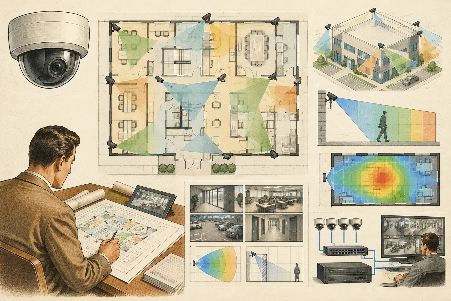
A camera coverage validation review is where a CCTV drawing becomes an engineering deliverable rather than a collection of camera symbols and field-of-view cones. It tests whether the proposed design can achieve its stated observation objectives after real walls, openings, obstructions, optical limits, and mounting constraints are considered.
The review should happen before procurement and installation, when a change to focal length, mounting position, or camera quantity is still relatively straightforward. It does not guarantee installed performance or regulatory acceptance. It does create a traceable basis for technical decisions, stakeholder comments, and site verification.
What a Camera Coverage Validation Review Should Prove
A useful review begins with an explicit question: what must each camera achieve at each relevant location? General monitoring of a lobby, recognition at a reception desk, and identification at a controlled doorway are different design objectives. A camera may see an area while still failing to provide the pixel density required for the required task.
The review therefore connects the drawing to measurable inputs. These normally include the calibrated plan scale, camera location, mounting height, direction, tilt, sensor size, resolution, focal length, and the target pixel density or DORI objective. DORI provides a practical framework for discussing whether detail is sufficient for detection, observation, recognition, or identification, but project teams must still define the required outcome for each scene.
A reviewer should be able to see three things clearly: the intended coverage area, the calculated quality of coverage within it, and the assumptions behind the calculation. Without those three elements, a colored cone on a plan can be visually persuasive but technically incomplete.
Start With Verified Drawing Geometry
Coverage calculations are only as dependable as the underlying geometry. If a floor plan has been imported at the wrong scale, every calculated distance, field of view, and pixel-density result will be wrong by the same proportion. This is why scale calibration should be completed before camera placement is assessed.
Use a known dimension from an architectural drawing or a physically verified reference distance. Then review the plan for walls, glazed partitions, doors, counters, columns, racking, machinery, and other features that can affect visibility. A wall is not simply a drafting line. In coverage validation, it is an occlusion boundary unless the opening or transparent section has been deliberately modeled and its operational condition is understood.
Geometry also needs the right level of detail for the design stage. A concept design may reasonably model primary walls, doors, and major equipment. A construction-stage review should account for fixed joinery, storage zones, turnstiles, ceiling bulkheads, and other known obstructions. The right question is not whether every object has been drawn. It is whether omitted objects could change the security outcome.
Check mounting constraints early
A mathematically suitable camera location may not be installable. Ceiling structure, lighting, fire systems, access panels, architectural finishes, and cable routes can all force a change. Confirm that the proposed mounting point can be reached, serviced, and coordinated with the project team.
Mounting height and tilt require particular attention. Raising a camera can widen its visible floor area, but it may reduce facial detail at critical points or introduce views blocked by soffits and fixtures. A lower mounting height may improve target detail while increasing the risk of tampering or local occlusion. There is no universal best height. It depends on the scene, target distance, lens selection, and operational requirement.
Validate Field of View Against Pixel Density
Field of view answers where the camera can see. Pixel density, commonly expressed as pixels per meter or PPM, answers how much image detail is available across that scene. Both need to be reviewed together.
A wide-angle lens may provide broad situational awareness across a parking area or open office. At the far edge, however, the image may not support the same DORI objective as the center or near field. Conversely, a narrow focal length can provide stronger detail at a doorway while leaving approach routes and adjacent areas outside the usable field of view.
For each camera, review the coverage at meaningful target locations rather than relying on a single average result. These locations may include a door threshold, a cash-handling point, an elevator landing, a vehicle entrance, or the far end of a corridor. Confirm the scene distance, calculate the expected PPM using the selected camera parameters, and compare the result with the project requirement.
This approach also prevents a common specification problem: selecting a camera based only on resolution. Resolution matters, but it does not independently determine usable scene detail. Sensor size, focal length, distance, aspect ratio, scene width, mounting angle, compression settings, lighting, and manufacturer image processing can all affect actual results. Calculated PPM is a design input for review, not a substitute for commissioning tests in site conditions.
Identify Blind Spots and Question Overlap
Blind spots are not always design failures. Some may be accepted because the area has no security requirement, is physically inaccessible, or is covered by another security measure. The important point is that they are visible, documented, and accepted by the appropriate project stakeholders rather than discovered after handover.
Look beyond obvious corners. Blind spots often occur behind door swings, at the base of stair cores, beneath canopies, around high shelving, between cameras with parallel views, and at transitions between indoor and outdoor areas. A plan-view field of view may also hide a vertical issue, such as a high vehicle blocking a lower camera's line of sight or a camera tilt that misses a person's face at an entry point.
Coverage overlap deserves equally careful treatment. Overlap can provide continuity when a person moves between zones, reduce risk from temporary occlusion, and support incident review from more than one angle. But overlap also has a cost in camera count, storage, network capacity, and installation complexity. Two cameras seeing the same general area is not automatically useful redundancy if neither provides the required detail at the critical target.
A sound review distinguishes purposeful overlap from accidental duplication. Purposeful overlap should have a stated role, such as covering opposite sides of a doorway, maintaining tracking continuity along a route, or providing a secondary view of a transaction point.
Review the Design as a System, Not a Plan Markup
Camera coverage is connected to the rest of the CCTV design. A revised lens or camera location can affect cable length, PoE budget, switch location, network topology, recording bandwidth, storage estimates, and camera schedule data. Treating coverage review as an isolated drawing exercise creates inconsistencies that appear later in procurement or installation.
This is where a persistent design workspace is useful. In CCTV Design Tool Online, a team can import and calibrate a drawing, model relevant geometry, configure brand-agnostic camera parameters, and review field of view, DORI, pixel density, blind spots, and overlap in the same project record. The value is not automation for its own sake. It is traceability between the design decision, the underlying inputs, and the report issued for review.
When using automated or AI-assisted geometry suggestions, verify the detected walls, openings, scale, and camera assumptions before accepting the output. Automation can accelerate repetitive work, but it cannot determine the operational importance of a doorway, the likely height of stored goods, or a project-specific security requirement without professional review.
Issue a Review Package That Can Be Checked
A camera coverage validation review should result in a deliverable that another professional can interrogate. At minimum, include the calibrated drawing, camera identifiers, coverage visuals, camera schedule, stated DORI or PPM criteria, key assumptions, blind-spot observations, and unresolved coordination items.
For complex sites, add zone-based commentary. A reviewer should not have to infer why one camera is aimed at a loading dock gate while another covers the wider maneuvering area. State the intended purpose and any limitations, such as reduced detail beyond a defined distance or reliance on lighting that has not yet been confirmed.
Version control matters. If architecture changes, walls move, a door is reversed, or a camera model is substituted, revalidate the affected views and record the revision. A report is only defensible when it corresponds to the design actually being issued.
The most valuable outcome is not a plan with more coverage shading. It is a design that makes its assumptions visible, exposes decisions before they become site rework, and gives installers, consultants, and project owners a clear basis for the next technical conversation.