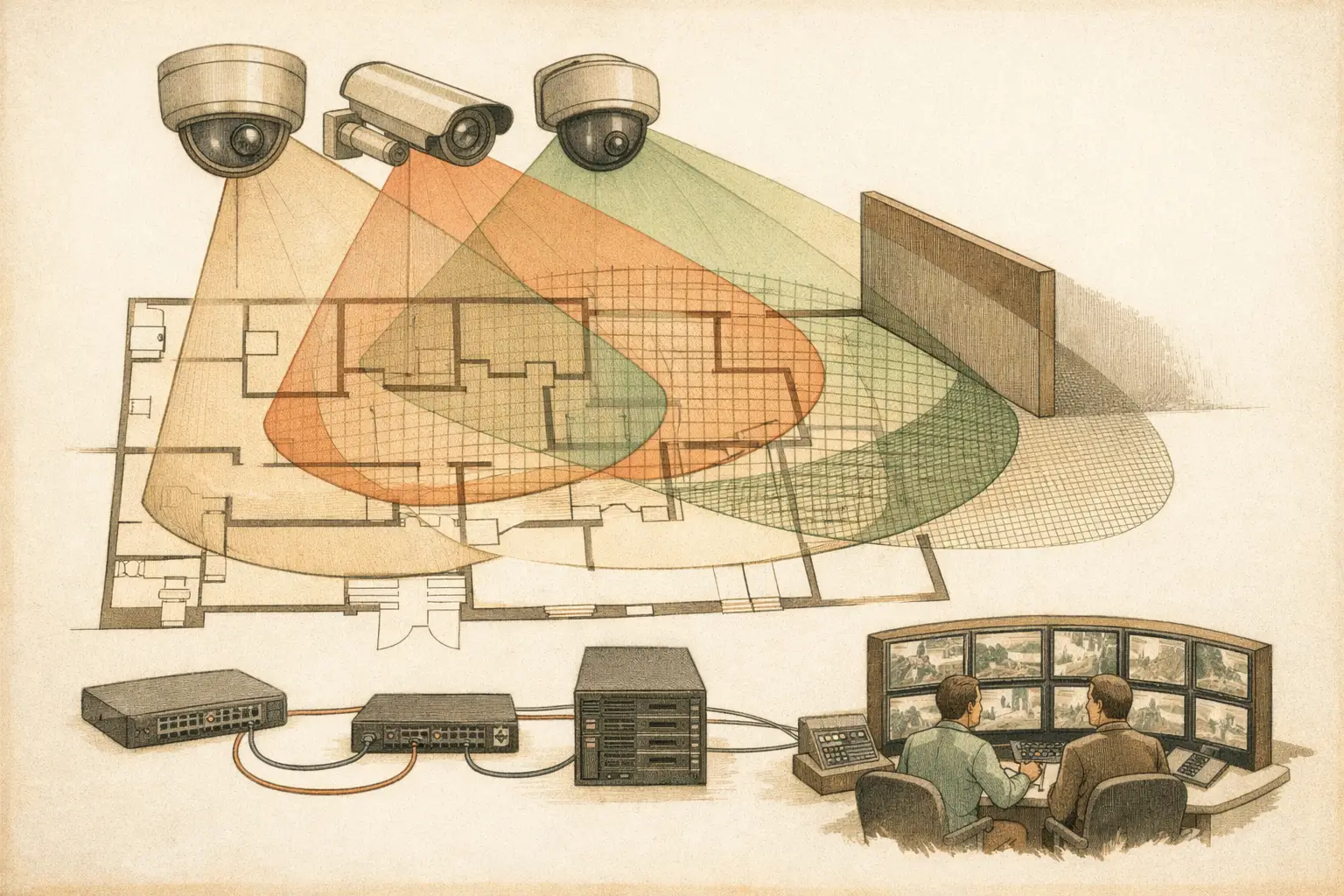
A coverage drawing can show every corridor, doorway, and perimeter line inside a camera field of view yet still leave the security objective unsupported. The usual cause is not too few cameras. It is poorly planned camera overlap for surveillance coverage: cameras see the same broad area without providing a usable second view where identification, continuity, or occlusion resilience is actually required.
Overlap is often treated as a visual preference, represented by intersecting camera cones on a floor plan. In an engineering design, it is a deliberate relationship between two or more cameras, their pixel density, viewing angle, mounting geometry, scene conditions, and the operational task assigned to that location.
What camera overlap is meant to achieve
Coverage overlap exists when more than one camera can observe part of the same physical area. That shared area may be a narrow strip at a doorway, a vehicle lane at a gate, a transaction point, or a wider zone in an open lobby. Its value depends on what each camera contributes.
A second view can preserve observation when a person, vehicle, shelving unit, door leaf, or temporary object blocks the primary camera. It can also provide a more favorable angle for facial detail, direction of travel, or activity interpretation. At critical entries, overlap helps maintain visual continuity as a subject moves from one camera scene into the next.
This does not mean every camera should duplicate the next. Excessive overlap can waste camera count, increase storage and network demand, and complicate operator review. Two wide views of the same area may add less value than one carefully positioned camera covering an adjacent blind spot at the required pixels per meter, or PPM.
The design question is therefore not, "Do the field-of-view cones touch?" It is, "At the required location, does the combined coverage support the intended security task under realistic geometry?"
Start with operational objectives and DORI
Before setting an overlap percentage, define the task for each scene. DORI provides a useful design language: detect, observe, recognize, and identify. These categories should be interpreted against the project brief and the applicable camera performance assumptions, not as a promise of real-world outcome.
For example, an external parking area may need detection coverage across the full lot, while a pedestrian entrance needs recognition or identification capability at the expected approach path. A camera looking across the lot may overlap an entrance camera, but the overlap only has practical value if its pixel density at the entrance supports a meaningful secondary task.
This distinction prevents a common error: relying on a distant overview camera as backup for an identification camera. The overview may record movement and context, but its sensor size, focal length, resolution, and subject distance may provide insufficient PPM for a face or other detail required by the brief.
Use calculated DORI and pixel-density results to label each camera's role. Then review the shared areas. A useful overlap might pair:
- a context camera with a detail camera at a reception desk;
- two directionally opposed cameras covering a doorway and its immediate approach;
- adjacent corridor cameras that maintain continuity along the travel path; or
- perimeter cameras that retain observation when a vehicle or landscaping feature causes occlusion.
The required relationship differs by scene. A gate often benefits from both overview and detail coverage. A narrow corridor may benefit more from planned handoff between adjacent cameras. An open warehouse may need selective overlap at cross-aisles and loading points rather than repeated broad views across empty floor area.
Design overlap around real geometry
A camera cone drawn on an uncalibrated plan is only an illustration. Reliable coverage analysis starts when the drawing scale is calibrated and walls, doors, partitions, racking, columns, and other physical geometry are reviewed. These objects shape what the camera can see.
Mounting height, tilt, camera direction, sensor size, focal length, and resolution should be entered as design inputs. A small change in focal length can materially alter scene width and PPM. Similarly, changing a camera from a ceiling mount to a wall mount can alter the angle at which people are seen and introduce new occlusions near door frames or soffits.
At each intended overlap zone, examine three conditions. First, confirm that both cameras have an unblocked line of sight to the critical area. Second, compare their pixel density at that point. Third, consider the viewing angle. Two cameras may both cover a doorway, but if both look at a person's back as they enter, the overlap is less useful than views from complementary directions.
Doors deserve special attention. A closed door may conceal an approach route; an open door can block a camera near the frame. Revolving doors, turnstiles, counters, display fixtures, and vehicle barriers create similar effects. The design should model fixed obstructions and identify foreseeable operational obstructions, while recognizing that temporary conditions on site cannot be fully predicted from a plan.
Use overlap zones, not arbitrary percentages
There is no universal percentage of overlap that suits every CCTV project. A rule such as 10% or 20% may be a starting convention for a continuous corridor, but it is not an engineering requirement by itself. The appropriate amount depends on the target location, camera purpose, and scene geometry.
For a corridor handoff, overlap should be sufficient to avoid an unobserved gap between camera scenes as a subject walks through the space. For a doorway, the overlap zone may be deliberately concentrated around the threshold and approach direction. For a large open area, only selected risk points may require dual coverage.
Define these areas visibly on the plan. Instead of stating that two cameras overlap, document what they overlap over: "north lobby entry threshold," "loading dock pedestrian crossing," or "server room access side." This creates traceability between the camera layout and the project security objectives.
Where the project requires an alternate perspective, avoid mounting both cameras on the same line of sight. A modest separation in position or direction can reduce the chance that one obstruction affects both views. The trade-off is that large angular separation may create inconsistent facial presentation, lighting response, or scene perspective. The best arrangement depends on the target and the conditions expected during operation.
Check lighting, motion, and scene behavior
Geometric overlap is calculated from the plan and camera specifications. Actual field performance is also affected by lighting, reflections, motion blur, compression settings, lens quality, camera configuration, and installation tolerances. A design model cannot establish how every scene will perform at night or during a high-contrast sunrise without appropriate verification.
This is particularly relevant when cameras view glazed entrances, vehicle headlights, reflective floors, or strong backlighting. Two overlapping cameras can share the same exposure problem if they face the same light source. A complementary angle may provide a more useful fallback, but it should be assessed during commissioning.
Also consider how people and vehicles move. A camera can meet a pixel-density target at one point while observing a subject only briefly or at an unfavorable angle. Place overlap where subjects naturally slow, turn, present their faces, transact, enter, exit, or cross between zones. These are often more valuable locations than the visual center of a room.
Coordinate overlap with network and recording design
Every additional camera and every higher-resolution scene affects the network topology, switch port capacity, PoE budget, uplink demand, recording bandwidth, and storage calculation. Coverage decisions should not be isolated from the ICT and video-management design.
This does not mean reducing overlap solely to minimize bandwidth. It means documenting why each overlapping camera exists and checking whether its stream characteristics are proportionate to its task. An identification-focused scene may justify more detail than a broad situational-awareness view. Recording policies, frame rate, bitrate controls, and retention requirements should be established by the project team and verified against the selected equipment.
A coordinated design also makes installation clearer. Camera IDs, mounting locations, fields of view, coverage roles, cable routes, network connections, and recording assumptions should agree across drawings, schedules, and reports. Inconsistencies between these documents are a frequent source of site rework.
Review overlap in a repeatable design workflow
A disciplined workflow begins by importing and scale-calibrating the drawing. Review walls and physical geometry, position cameras, and configure the available technical parameters rather than relying on generic cone shapes. Then assess field of view, DORI, PPM, blind spots, occlusions, and shared coverage zones against each operational objective.
CCTV Design Tool Online supports this type of persistent design workspace by bringing geometry, camera specifications, visual coverage analysis, network planning, and technical documentation into the same process. The calculated results remain design guidance. Final device selection, installation details, site conditions, and any jurisdiction-specific requirements require review by qualified professionals.
Before issuing a layout, ask whether every overlap zone has a stated purpose, whether each camera adds a distinct view or density level, and whether physical obstructions have been considered. Then carry those decisions into a structured deliverable that another designer, installer, reviewer, or project owner can follow.
Well-designed overlap is not duplicated video for its own sake. It is an intentional layer of resilience and evidence quality, placed where the real movement paths and security decisions occur.