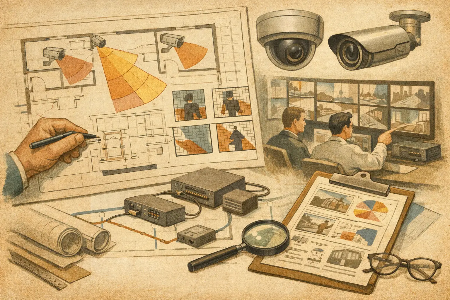
A camera symbol on a floor plan is not design evidence. It does not show whether a wall blocks the view, whether the focal length supports the intended task, or whether the proposed network can support the camera load. Effective CCTV documentation practices turn design intent into a traceable record that installers, reviewers, ICT teams, owners, and future maintenance personnel can interpret without reconstructing the designer’s assumptions.
For security projects, documentation is not an administrative task completed after the design. It is the control layer between a calculated model, an installed system, and the operational requirement. When it is incomplete, small changes in mounting height, camera direction, lens selection, or room layout can become expensive coordination issues on site.
What CCTV Documentation Must Prove
A useful CCTV package should let a reviewer answer three questions quickly: what is proposed, why it is proposed, and what assumptions affect the result. The required level of detail depends on the project stage. A concept design may establish surveillance objectives and preliminary camera zones. A tender or construction package needs coordinated positions, schedules, coverage evidence, and defined interfaces.
The key distinction is between a visual indication and an engineering record. A plan with camera cones may communicate intent, but it is not enough if the cones have not been checked against scale, walls, openings, mounting conditions, and camera parameters. Similarly, a camera schedule is not reliable if its identifiers do not match the drawings and its specifications do not reflect the coverage requirement.
Calculated field of view, pixel density, and DORI results are design outputs based on the inputs used. They should be presented as such. Actual field performance can vary because of installed camera position, final lens adjustment, lighting, scene contrast, weather, compression settings, maintenance condition, and manufacturer-specific analytics behavior. Documentation should make that boundary clear rather than implying a calculation guarantees operational performance.
Start With a Controlled Drawing Basis
Every dependable document set begins with the drawing basis. Record the source drawing, revision reference, date received, and the level or area it represents. If a PDF, image, or CAD export has been imported into a design workspace, document the scale calibration method and the reference dimensions used.
Scale calibration deserves particular attention. An apparently minor error can distort field-of-view distances, mounting locations, cable estimates, and coverage areas across an entire floor. The drawing should also identify assumptions where dimensions are incomplete, geometry is conceptual, or future fit-out remains undefined. A reviewer needs to know whether a camera is coordinated to an issued architectural plan or positioned against a preliminary layout.
Build a stable camera identification system
Camera IDs must remain consistent across plans, schedules, network diagrams, elevations, reports, and commissioning records. A clear convention might distinguish buildings, levels, systems, or camera types, but the format matters less than stability. Avoid renumbering cameras late in a project solely to make the schedule look tidy. That can break coordination with cable labels, switch-port assignments, VMS configuration, and installer markups.
Where a camera is moved, replaced, or removed, record the revision and reason. A revision cloud alone does not explain whether the change was driven by an architectural clash, an updated security requirement, an occlusion, or a revised field-of-view calculation.
Document Coverage as Measurable Design Intent
Coverage drawings are most useful when they link the surveillance objective to a defined scene area. Rather than labeling broad areas as “covered,” identify the relevant target: a door threshold, reception desk, vehicle gate, loading bay, perimeter approach, corridor intersection, or cash-handling point.
For each critical view, record the camera location, mounting height, direction, tilt, focal length, sensor size, resolution, and calculated field of view. State the required pixel density in PPM where the task requires it. DORI can help communicate whether the modeled scene is intended for detection, observation, recognition, or identification at a selected distance, provided the project team understands it is a design framework rather than a substitute for site validation.
A good drawing also shows what the camera cannot see. Walls, columns, ceilings, racking, doors, landscaping, parked vehicles, and other physical obstructions create occlusion. Mark material blind spots when they affect the stated security objective. This is more credible than presenting every camera as an unrestricted cone across the plan.
Coverage overlap requires judgment. Overlap may be justified at entry points, high-value zones, transition areas, or locations where one camera could be obscured. Elsewhere, excessive overlap can add cost, storage demand, network load, and review complexity without improving the operational outcome. The document should explain the intent of any significant overlap rather than treating more coverage color as automatically better coverage.
Separate design geometry from site verification
Camera placement models work from the available physical geometry and specified parameters. They cannot confirm every condition that will exist after construction. A pendant mount may be relocated around services, a finished ceiling height may differ from the coordinated drawing, or signage may obstruct a view that was clear during design.
For that reason, include a site verification stage in the documentation workflow. Before final acceptance, verify camera position, mounting height, aim, focal length or varifocal setting, visible obstructions, lighting conditions, and the final scene against the approved design intent. Record approved deviations and update as-built documents accordingly.
Make the Camera Schedule a Coordination Tool
The camera schedule is often the most frequently used document after installation begins. It should be structured so that a technician, project manager, and reviewer can all identify the same device and understand its purpose.
At minimum, each entry should align its camera ID, location, protected area or view description, mounting type, mounting height, direction, tilt, resolution, sensor size, focal length or lens range, and required pixel-density target where applicable. Include the relevant network, recording, or power reference if those elements are developed at the same stage.
Avoid copying generic product descriptions into the schedule without checking them against the modeled design. A camera can have adequate resolution on paper while its chosen focal length produces insufficient pixel density at the target distance. Conversely, a narrow lens selected only to meet a distant recognition objective may leave a nearby access route outside the required field of view. The schedule should show the engineered selection, not merely a catalog category.
Manufacturer-specific items should be verified against the applicable official datasheet before procurement. Documenting technical parameters does not remove the need to confirm availability, firmware compatibility, environmental rating, or final product suitability through the normal project process.
Connect CCTV Records to Network and Power Decisions
A surveillance design becomes difficult to deliver when camera plans and ICT information are maintained separately. The CCTV documents should show enough network context to support coordination: cabinet or communication room references, switch locations, camera network allocation, primary cable pathways, and relevant uplink relationships.
The level of detail depends on scope. A security consultant may document network topology and estimated requirements, while an ICT designer produces the detailed switch configuration and cable design. What matters is that the handoff is explicit. If bandwidth, PoE demand, storage retention, multicast behavior, redundancy, or cybersecurity controls are outside the CCTV designer’s scope, identify the responsible discipline and the assumptions that require confirmation.
This avoids a common failure point: a camera layout is approved visually, then later cannot be connected through the available containment, switch capacity, or power budget. Documentation does not solve every interface issue, but it makes ownership and dependencies visible early.
Issue Documents That Support Each Project Stage
The same report should not be expected to serve every stage unchanged. Early-stage documents should communicate risk, scope, coverage intent, and open assumptions. Detailed design documents should provide coordinated camera layouts, schedules, field-of-view evidence, blind-spot observations, and network planning references. Construction-stage packages need clear issue status and revision control. As-built records must describe what was actually installed, including accepted deviations.
A disciplined issue register is often more valuable than an overly polished report. State the document revision, issue purpose, drawing list, outstanding decisions, exclusions, and inputs requiring confirmation. This gives project owners and reviewers a reliable basis for comments and reduces the chance that an outdated export is used on site.
A persistent design workspace can reduce drift between the floor plan, camera schedule, visual coverage analysis, and report outputs. For example, CCTV Design Tool Online brings physical geometry, field of view, DORI and PPM calculations, camera parameters, and network planning into one design record. Even then, the resulting documentation should be reviewed by qualified professionals against the project brief, final drawings, and applicable jurisdictional requirements.
Treat Documentation as a Living Engineering Record
The strongest CCTV documentation practices do not aim to make a proposal look complete. They make decisions visible, testable, and maintainable. When a future reviewer can trace a camera from its security objective through its field of view, pixel-density requirement, mounting assumptions, network connection, and final site verification, the documentation has done its job.
That traceability gives the project team a practical way to manage change: revise the input, review the effect on coverage and coordination, then issue a controlled record that everyone can use.