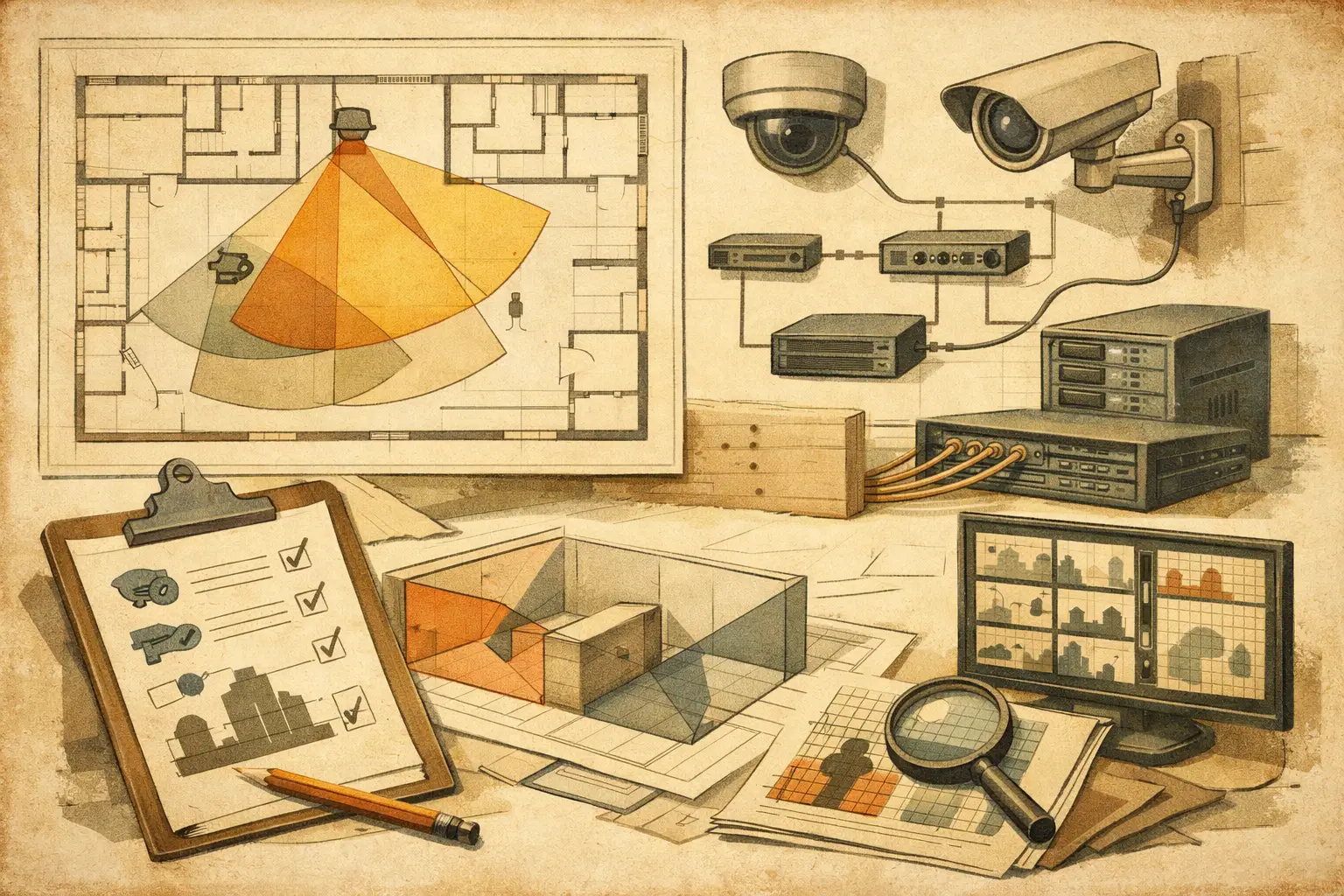
A permit reviewer cannot approve a camera cone floating on an unscaled floor plan. They need to understand what will be installed, where it will be installed, what it can see, how it connects, and whether the proposal coordinates with the building and project conditions. CCTV permit documentation requirements therefore extend beyond a camera schedule. They are a traceability exercise connecting the design intent to physical installation information.
The exact submission package depends on the jurisdiction, project contract, building type, and authority having jurisdiction. Some projects require a formal permit submission, while others require only consultant approval, client review, landlord consent, or coordination with an electrical, ICT, or low-voltage permit package. A qualified professional should verify current local requirements before submission. The practical objective is consistent in every case: provide drawings and technical records that allow a reviewer to assess the proposed system without reconstructing the design from separate files.
Start With a Permit Documentation Matrix
Before producing drawings, establish who is reviewing the package and what each reviewer needs. A city permit office may focus on building work, electrical pathways, exterior equipment, and public-facing installations. A client security team may focus on DORI performance, recording capacity, and operational coverage. The ICT consultant may need network topology, switch locations, power-over-Ethernet loading, and backbone routes.
Create a documentation matrix with the submission item, responsible discipline, drawing or report reference, revision status, and reviewer requirement. This prevents a common coordination failure: the camera layout is complete, but the containment route, equipment-room space, or network connection detail is absent.
The matrix should also identify project-specific constraints, such as listed architectural areas, restricted façade penetrations, privacy boundaries, or requirements for approved equipment. Do not assume that a technical CCTV drawing alone answers those issues.
Core CCTV Permit Documentation Requirements
A well-organized package normally combines plans, schedules, calculations, and installation details. The level of detail should match the project stage. A concept submission may show design intent and camera zones, while a construction submission needs dimensions, mounting arrangements, device identifiers, and coordinated pathways.
Scaled camera layout plans
The layout plan is the primary review document. Import the current architectural plan, calibrate its scale against a verified dimension, and record the drawing revision used as the design base. A scale error affects mounting distances, field-of-view calculations, cable routes, and the credibility of the whole submission.
Show each camera with a unique identifier that matches the schedule. Include its mounting location, direction, mounting height, and a field-of-view representation. The field of view should respond to walls, partitions, and other modeled obstructions where geometry is available. A cone that passes through a solid wall may be visually convenient, but it does not communicate usable coverage.
Where the installation is exterior, show the camera relationship to property lines, access roads, entrances, gates, and neighboring areas where relevant. The purpose is not to make legal conclusions about privacy. It is to make the intended viewing area clear so that the owner and relevant reviewers can assess the design against project rules and applicable law.
Camera schedule and technical basis
The schedule converts symbols on a plan into procurement and installation information. At minimum, each line should identify the camera ID, location, camera type, resolution, sensor size where known, focal length or lens range, mounting height, direction, tilt, and intended coverage purpose.
Include calculated field-of-view dimensions and the pixel density at the relevant target area when the design is based on a measurable operational objective. PPM, or pixels per meter, provides a useful engineering measure. DORI can help describe whether a scene is intended for detection, observation, recognition, or identification. These are calculated design results, not a guarantee of field performance. Scene illumination, compression, movement, lens quality, installation tolerance, and VMS configuration can materially change real-world results.
If a manufacturer and model have been selected, use verified data from the current official datasheet. If the design remains brand-agnostic, state the required technical parameters instead of implying a specific product will meet the requirement.
Coverage and occlusion evidence
Reviewers often need more than a nominal camera angle. They need to see whether critical routes, doors, counters, loading zones, or perimeter lines are covered at the required detail level. Provide annotated coverage plans for the principal security objectives and identify blind spots that remain by design.
Coverage overlap also deserves explanation. Overlap may be intentional at entrances, cash-handling areas, or high-risk transition zones to preserve observation if one view is obstructed. Elsewhere, excessive overlap can add cost and network load without improving the operational outcome. The drawing should distinguish deliberate redundancy from accidental duplication.
For complex spaces, include elevation views, sections, or perspective images. A plan view may not reveal that a camera at a proposed mounting height is blocked by a soffit, racking, signage, a door swing, or a structural beam. Record meaningful occlusions and any assumptions requiring site verification.
Equipment, power, and network documentation
A permit or coordinated construction package should show where the system equipment resides and how devices connect. This typically includes camera connections, field cabinets where applicable, communications rooms, recording or management equipment, switches, uplinks, and relevant power sources.
The topology should identify the network segments and main routes clearly enough for ICT and electrical coordination. It does not need to expose unnecessary cybersecurity detail in a broadly circulated drawing set. However, the package should not hide dependencies such as a remote switch requiring local power, a long copper run that may exceed the selected technology’s design limits, or a camera location that requires a new pathway.
Where a power calculation, heat-load review, UPS assessment, or storage calculation is required by the project, include it as a referenced technical appendix or coordinate it with the responsible discipline. Avoid presenting generic assumptions as confirmed site conditions.
Installation details and coordination drawings
Camera placement becomes buildable only when the mounting method and pathway interface are defined. Provide typical details for ceiling, wall, pole, parapet, or external façade mounting as applicable. Show intended conduit or cable-tray interfaces, junction boxes, weather protection where specified, and the relationship to ceilings or structural elements.
Details should be coordinated with architectural, structural, electrical, fire protection, and mechanical drawings. A camera may satisfy DORI on a security plan but still conflict with an access panel, sprinkler clearance, lighting fixture, or decorative ceiling feature. Resolve these conflicts before the issue reaches the installer.
Build a Traceable Review Package
A reviewer should be able to follow a simple chain: security objective, camera location, camera specification, calculated coverage, connection method, and installation detail. Revision control keeps that chain intact. Every submitted document should carry a project name, date, revision code, status, and drawing reference.
Use consistent camera IDs across plans, schedules, topology diagrams, reports, and bill-of-material references. If Camera C-014 moves because of a ceiling conflict, update its position, mounting height, field of view, schedule entry, cable route, and any related calculation. Partial updates are a frequent source of installation rework and disputed scope.
A browser-based design workspace such as CCTV Design Tool Online can support this workflow by retaining calibrated plans, modeled walls, camera parameters, field-of-view analysis, DORI and PPM outputs, and report content in one design record. The calculations still require professional review, especially when existing drawings, physical obstructions, or site conditions are uncertain.
Review Before Submission
Run an internal review against the documentation matrix before issuing the package. Confirm that the floor-plan revision is current, scale calibration has been checked, camera IDs are unique, and every critical area has an explicit coverage objective. Check that field-of-view diagrams account for known physical geometry and that no schedule value contradicts the plan.
Then review the project-specific submission instructions. Some authorities or owners require signed forms, licensed-professional involvement, equipment cut sheets, electrical drawings, or a particular digital file format. Those items are jurisdictional or contractual requirements, not universal CCTV engineering rules.
The strongest CCTV submission is not the one with the most pages. It is the one in which a reviewer can quickly verify the design basis, identify assumptions, and request a focused clarification rather than guess how the system is meant to be installed.