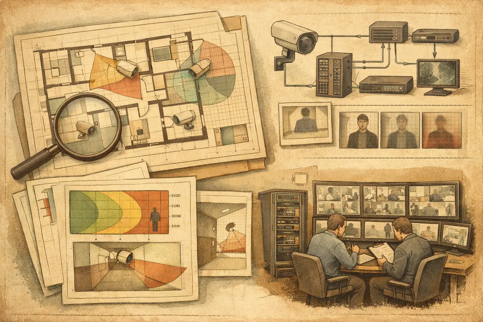
A CCTV design report is often judged before anyone opens the floor plan. If the document does not clearly connect the project brief, camera schedule, field-of-view analysis, and network requirements, a reviewer cannot reliably determine what has been designed or why. This CCTV report sections checklist provides a disciplined structure for turning design inputs into a traceable technical deliverable.
The right level of detail depends on the project stage. A concept report may document proposed coverage zones and assumptions, while an installation issue package needs coordinated camera identifiers, mounting details, cable pathways, and equipment requirements. In both cases, the report should distinguish calculated design results from conditions that must be verified on site.
Start with report control and project scope
Every report should identify the project, issue date, revision number, author, reviewer, and document status. This is basic document control, but it prevents a common coordination problem: an installer works from a superseded camera layout while a consultant reviews a newer schedule.
The scope statement should define the areas included, the security objectives being addressed, and the intended design stage. State whether the report covers a new installation, an extension, a coverage review, or an as-built verification. It should also identify exclusions, such as access control integration, civil works, monitoring procedures, recording retention, or third-party network infrastructure where those items are outside the assignment.
A concise design basis is useful here. Record the available drawings, site information, stakeholder brief, and reference documents used. If a floor plan has been scale-calibrated from a drawing, say so, and identify the calibration reference. A dimension taken from an unverified PDF should not be presented with the same certainty as a surveyed dimension.
Document assumptions and design criteria
CCTV performance begins with an operational purpose, not a camera model. The report should state what each coverage area is expected to support: monitoring activity, detecting a person, observing movement at a boundary, recognizing a known individual, or identifying a subject. These requirements drive pixel density, field of view, focal length, and mounting position.
Define the design criteria used for the analysis. This may include required PPM values, the DORI basis adopted for the project, minimum illumination assumptions where relevant, mounting height limits, and viewing directions. Avoid presenting generic DORI values as a regulatory requirement. DORI is a useful design framework, but the required outcome and any mandated criteria must be verified against the project brief and applicable local requirements.
The assumptions section should also address conditions that affect real-world results but may not be fully represented in a drawing. Examples include shelving that may change, parked vehicles, landscaping growth, seasonal glare, doors that can be open or closed, and architectural finishes that influence reflected light. A coverage calculation can model geometry accurately only to the quality of its inputs.
CCTV report sections checklist: drawings and geometry
The drawing section should allow a reader to understand the physical basis of the design without searching through multiple files. Include a key plan where needed, followed by level plans, site plans, elevations, or reflected ceiling plans appropriate to the installation.
Show camera locations with unique identifiers that match the schedule. Indicate camera direction, field of view, coverage range, mounting height, and tilt where the drawing scale supports it. Camera cones alone are not enough. They should account for walls, solid partitions, building geometry, and known obstructions so that apparent coverage is not mistaken for line-of-sight coverage.
Use clear legends and avoid placing too much information on one sheet. On larger sites, separate overview drawings from detailed area drawings. An overview can establish system intent, while detailed sheets make it possible to check entrances, cash-handling points, loading bays, perimeter gates, corridors, and other operationally significant areas.
Where coverage overlap is intentional, label its purpose. Overlap may support handoff between cameras, reduce blind spots near an entrance, or provide an alternate view of a critical area. It also has a cost and bandwidth implication, so it should be justified rather than added by habit.
Include a camera schedule that can be installed
The camera schedule is the bridge between design review, procurement, installation, and commissioning. Each row should use the same camera ID shown on the drawings and should record enough technical information to avoid ambiguity.
For each camera, include the location or coverage description, camera type, resolution, sensor size, focal length or varifocal range, mounting height, direction, tilt, target coverage distance, and intended DORI or PPM performance. Add the planned network connection point, switch reference, and recording destination where these are available.
Do not substitute an unverified product name for engineering data. If the project is brand-agnostic or the final manufacturer has not been selected, use performance-based parameters and clearly mark manufacturer selection as pending. Even when a specific model is nominated, manufacturer datasheets and compatibility should be checked before procurement.
A schedule should also identify special environmental or installation constraints, such as outdoor exposure, vandal resistance requirements, low-light considerations, pole mounting, or restricted ceiling access. These conditions often affect the final camera housing, lens choice, mounting method, and cable route.
Present field-of-view, DORI, and blind-spot analysis
This is the section that explains whether camera placement supports the stated objectives. For each important view, show the calculated field of view and identify the target zone being assessed. A useful report does not merely state that an area is covered. It shows where pixel density is expected to meet the selected design threshold and where it decreases with distance.
DORI and PPM outputs should be read as calculated planning values based on the entered camera parameters, geometry, and scale calibration. Actual scene performance can vary because of image processing, lens tolerances, lighting, motion blur, compression settings, weather, installation accuracy, and camera configuration.
Identify blind spots openly. Some are unavoidable because of columns, racking, walls, vehicle movements, or privacy constraints. The report should state whether a blind spot is accepted, mitigated by another camera, or requires a design decision. This is more useful than presenting a visually clean plan that hides limitations.
Coordinate network, power, and recording requirements
A camera layout is not a complete CCTV design if it cannot be connected, powered, recorded, and supported. The network section should show the proposed topology at a level appropriate to the project stage. This can include edge switches, communications rooms, uplinks, cabinet references, fiber links, PoE assumptions, and the relationship between cameras, recording servers, and management platforms.
Provide calculated or estimated bandwidth and storage inputs with the assumptions behind them. Resolution, frame rate, codec, scene activity, recording mode, and retention target can materially change the result. Where final settings have not been agreed, present a design assumption rather than a fixed promise.
Power considerations should identify whether cameras are intended to use PoE, local power, or another method. Highlight long cable runs, outdoor cabinets, surge protection needs, and resilience requirements for coordination with electrical and ICT teams. Detailed electrical and cybersecurity design may sit in separate documents, but the CCTV report should make dependencies visible.
Record interfaces, coordination items, and decisions
Complex projects fail at interfaces. The report should identify coordination items with architecture, MEP, ICT, fire and life safety, access control, civil works, and operations. Examples include camera mounting plates, ceiling coordination, containment routes, network cabinet space, gate intercom views, and restrictions on views into sensitive areas.
Include a decision log or review register when the design is still developing. Record the item, responsible party, required action, and status. This creates a practical route from design review to construction documentation instead of leaving critical questions buried in meeting notes.
If privacy requirements or local surveillance rules apply, identify them as project considerations requiring confirmation by the client, qualified professionals, and relevant authorities. The report can show privacy masks or restricted viewing zones where instructed, but it should not claim legal compliance without a jurisdiction-specific review.
Finish with deliverables, limitations, and approval actions
End the report with a concise list of issued drawings, schedules, calculations, and appendices. State the design limitations plainly: the report is based on the supplied plans, stated assumptions, and calculated camera parameters; final mounting positions and scene conditions require site verification; and installation performance must be tested during commissioning.
A final review page should identify the actions needed before the next stage, such as confirming camera objectives, verifying mounting heights, approving coverage trade-offs, selecting equipment, or validating network capacity. CCTV Design Tool Online can help maintain this connection between calibrated drawings, camera geometry, DORI analysis, schedules, and report outputs in one design workspace.
A report earns confidence when another professional can follow the chain from requirement to camera position to calculated coverage to installation action. Build that chain deliberately, and revisions become easier to review rather than harder to control.