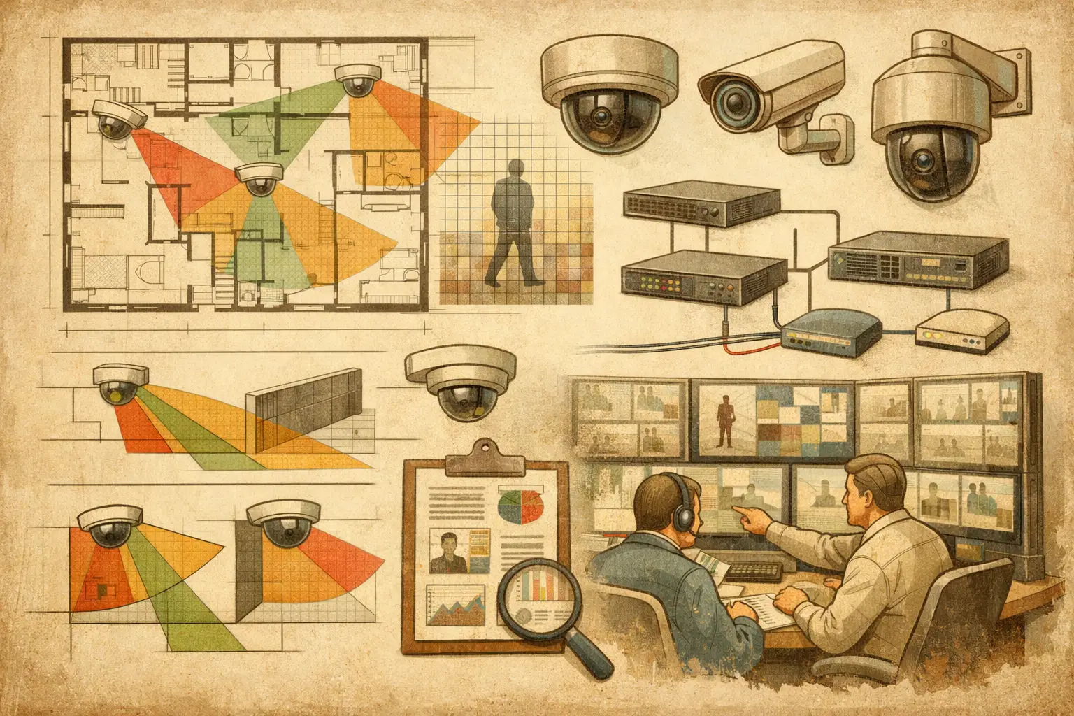
A security drawing with camera symbols is not yet a CCTV design. CCTV software becomes valuable when it connects each proposed camera to its field of view, optical settings, mounting position, physical obstructions, pixel-density target, network path, and documented design intent. That connection gives installers, consultants, and project owners a basis for reviewing what a system is expected to achieve before equipment reaches the site.
For projects with multiple floors, changing architectural drawings, mixed camera types, or several review stakeholders, this is more than a drafting convenience. It is a way to make design decisions traceable. The quality of the output still depends on accurate inputs, qualified review, and site verification, but the right workspace reduces the gaps created by separate CAD files, spreadsheets, screenshots, and manually maintained camera schedules.
What CCTV Software Should Do in a Design Workflow
The term CCTV software can describe many products, from video management systems to mobile camera viewers. For security designers, however, the relevant category is design and engineering software: a workspace used to plan, analyze, coordinate, and document a surveillance system before installation.
A practical design workflow begins with the architectural or site drawing. The drawing must be imported and scale-calibrated against a known dimension. If the scale is wrong, every subsequent result can be misleading: mounting distances, scene widths, coverage areas, cable runs, and calculated pixel density all inherit that error. Calibration is therefore an engineering control, not a setup detail.
Once the plan is correctly scaled, the designer can review walls, partitions, doors, glazing, columns, racking, fences, and other geometry that affects visibility. A camera cone drawn across a floor plan may look convincing while ignoring a masonry wall, a blocked corridor, or a change in elevation. Design software should help represent occlusion so that coverage is assessed against the physical environment rather than an empty diagram.
The output should be more than a marked-up plan. A useful system creates a consistent technical record that can include camera identifiers, locations, directions, mounting heights, focal lengths, sensor sizes, fields of view, DORI or PPM criteria, overlap areas, network assumptions, and report-ready drawings.
From Camera Symbol to Calculated Coverage
A camera icon says where equipment might be mounted. It does not establish whether a person, vehicle, doorway, or transaction point can be monitored at the required level of detail. That distinction is central to disciplined CCTV design.
Each camera needs defined technical inputs. Resolution, sensor size, focal length, mounting height, tilt, and direction work together to determine the scene captured. A wide-angle lens may provide broad situational awareness but lower pixel density across a distant target. A longer focal length can provide more detail at range but narrows the field of view and may create gaps between adjacent cameras.
Pixel density, often expressed as pixels per meter or PPM, gives the designer a measurable way to assess detail at a point or across an area. DORI - detection, observation, recognition, and identification - provides a related planning framework for describing operational expectations. These calculations support design decisions, but they do not replace a project-specific test of the selected camera, lens, scene lighting, compression settings, motion conditions, and recording configuration.
For example, an entrance camera intended to support recognition of people approaching a controlled door needs a different design objective than a parking-lot overview camera. Treating both as generic “coverage” can produce a system that looks complete on paper while failing to provide the detail needed for the intended use case.
Field of View Requires Physical Context
Field of view is not only a lens calculation. The camera position and the environment determine whether the useful view is available. A camera aimed down a corridor may lose visibility behind an open door. A lobby camera may have a clear geometric view but face backlighting from glazing. An outdoor camera may be affected by fence lines, landscaping growth, parked vehicles, or variable mounting conditions.
Good CCTV software helps the designer inspect the relationship between the coverage cone and plan geometry. It should make blind spots, blocked sightlines, and unnecessary overlap visible early, when repositioning a camera is a design decision rather than a site change request.
There is no universal rule that more overlap is always better. Some overlap supports continuity between cameras and reduces risk at transitions. Excessive overlap, however, can increase camera count, storage demand, switching capacity, and installation cost without improving the operational outcome. The appropriate balance depends on the threat assessment, scene layout, target activity, and client requirements.
Why Disconnected Tools Create Design Risk
Many teams still develop CCTV designs using a combination of CAD drawings, static PDF markups, spreadsheet schedules, manufacturer datasheets, image-editing tools, and separate calculation methods. Each tool may be capable on its own. The risk appears when a change in one place does not propagate to the others.
A revised focal length may alter the field of view but not the coverage diagram. A camera moved to avoid a beam may not be updated in the bill of quantities. A changed ceiling layout may introduce occlusion without triggering a review of camera angles. An ICT team may receive a network estimate that no longer matches the final camera count or resolution schedule.
An integrated workspace does not remove the need for coordination, but it gives the team a single design model to review. Camera parameters, placement, coverage calculations, and documentation can be updated from the same underlying project information. This is especially useful where security, architecture, electrical, and network disciplines are working through iterative design stages.
Network Planning Belongs in the Same Conversation
Camera placement decisions have network consequences. Higher resolution, frame rate, codec selection, scene complexity, retention period, and camera count all affect bandwidth and storage requirements. The physical route between a camera and its switch also affects PoE considerations, containment planning, cabinet locations, and topology decisions.
At concept stage, estimates may be based on reasonable design assumptions. At detailed design and procurement stages, those assumptions should be checked against the selected manufacturer’s current datasheets and the project’s actual recording, resilience, and cybersecurity requirements. CCTV design software can organize the inputs and expose dependencies, but it cannot validate a network architecture without complete project data and specialist review.
A useful workflow keeps camera schedules and network planning aligned. When cameras are added, removed, or reconfigured, the design team should be able to identify the effect on port counts, uplinks, storage estimates, and equipment-room capacity before issuing updated deliverables.
Choosing CCTV Software for Professional Use
The best choice depends on the project type and the maturity of the design process. A small residential installation may need a straightforward plan and camera schedule. A campus, transport facility, commercial tower, or industrial site needs stronger controls around revisions, coverage review, documentation, and multi-discipline coordination.
When evaluating a platform, focus on whether it supports the actual decisions your team must make. The following capabilities are usually more valuable than decorative 3D visuals alone:
- Accurate floor-plan import and scale calibration
- Camera configuration using technical parameters rather than a fixed brand catalog
- Field-of-view visualization that accounts for walls and other occlusions
- DORI and pixel-density analysis tied to defined coverage objectives
- Clear identification of blind spots and coverage overlap
- Camera schedules, network planning inputs, and structured technical reports
Brand-agnostic modeling is particularly useful during early design, tender, and independent review. It allows the team to define resolution, sensor size, focal length, and mounting assumptions without prematurely locking the project to one manufacturer. Final equipment selection should still be verified against official datasheets, available lens options, environmental ratings, and the project specification.
A More Defensible Design Review Process
CCTV Design Tool Online is designed around this engineering workflow: import and calibrate the drawing, review physical geometry, position and configure cameras, analyze field of view and DORI, assess blind spots and overlap, plan network relationships, and generate a structured deliverable. Its purpose is not to promise installation performance or authority acceptance. It is to give project teams clearer calculated evidence for design review and coordination.
For consultants, that evidence helps explain why a camera is located at a particular point and what coverage objective it supports. For installers, it reduces ambiguity between a symbolic plan and a technical installation intent. For project owners, it creates a more readable basis for comparing scope, understanding limitations, and requesting changes before construction.
The final design should always be checked against current site conditions. Ceiling heights can differ from drawings, furniture and signage can create new obstructions, lighting can change, and operational procedures can alter the areas that need meaningful coverage. Jurisdiction-specific requirements, privacy obligations, and authority conditions must also be reviewed by qualified professionals using the applicable project documents and official sources.
The useful question is not whether software can place cameras automatically. It is whether the design process makes each placement, field of view, and coverage expectation clear enough to review, challenge, coordinate, and improve before it becomes costly to change.