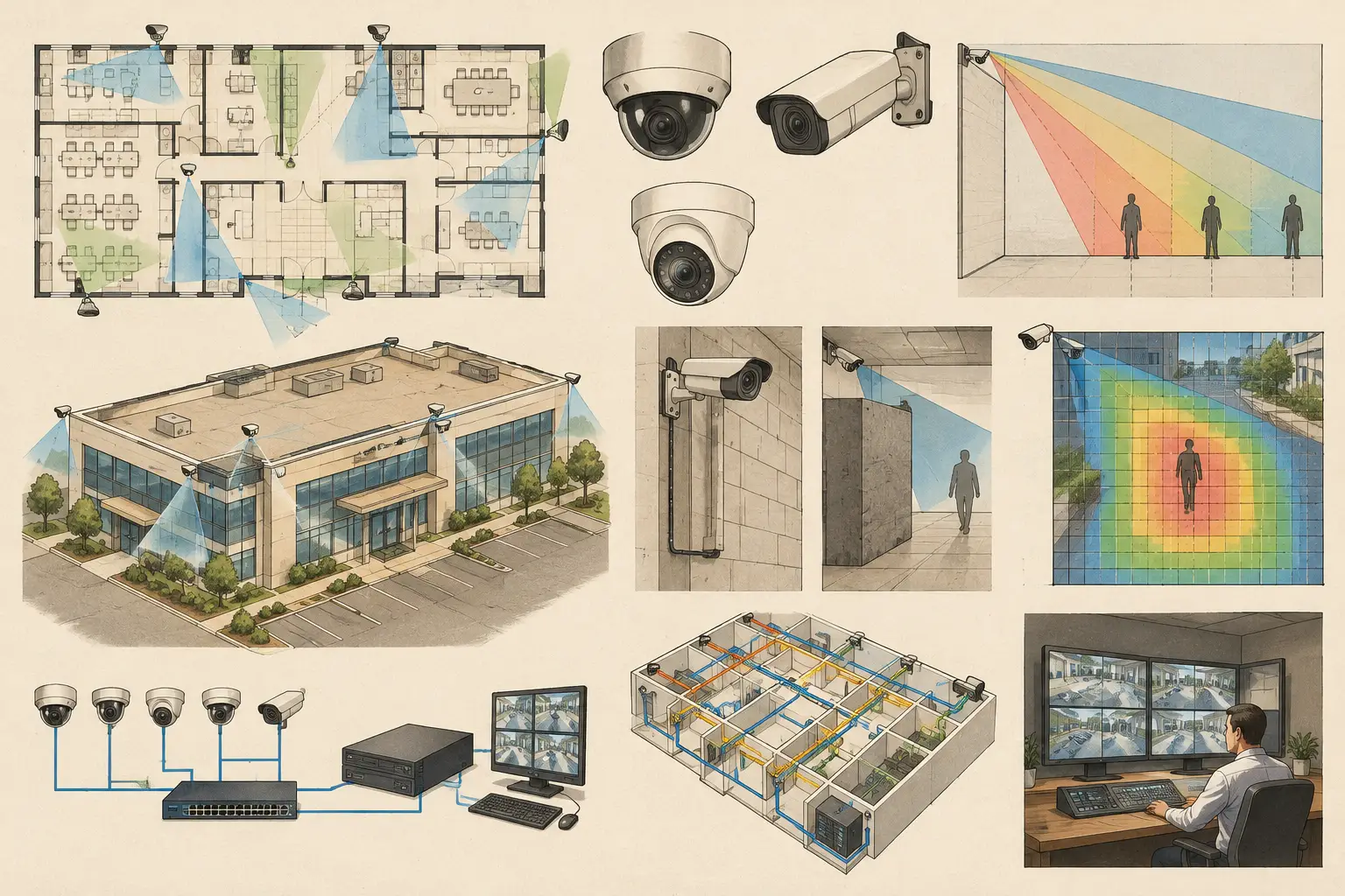
A commercial CCTV specification guide should begin with the operational question the system must answer, not with a preferred camera model or a generic resolution requirement. Can an operator observe activity at a loading dock? Must security identify a person at a controlled door? Is a vehicle plate required at a gate, and under what lighting and traffic conditions? These decisions determine the required pixel density, field of view, optics, placement, recording design, and acceptance evidence.
A specification that only states quantities such as “install 40 IP cameras” leaves the most significant engineering decisions to interpretation. A useful commercial specification creates traceability from the security objective to the camera schedule, floor plan, network topology, and final test records.
Define the security outcome before selecting equipment
Start by dividing the site into surveillance scenarios. Typical scenarios include perimeter observation, entrance control, reception monitoring, corridor coverage, cash-handling areas, loading bays, parking areas, and critical equipment rooms. Each has a different target distance, subject movement, lighting profile, privacy constraint, and evidence requirement.
For every scene, state what the camera is expected to achieve. DORI is a practical framework for this discussion: detection, observation, recognition, and identification. These categories should not be treated as interchangeable. A camera that supports detection across a wide parking area may not deliver recognition at the pedestrian entrance within that same view.
The specification should state the required pixel density, often expressed in pixels per meter or PPM, at the relevant target plane. It should also define the area where that requirement applies. “Minimum 250 PPM at the access-control reader zone” is more testable than “high-resolution camera at entrance.” Project teams should verify the applicable performance criteria against the client brief, risk assessment, and any jurisdiction-specific requirements.
Build the commercial CCTV specification around measurable inputs
A camera specification is not simply a resolution field. Resolution only describes the number of available image pixels. Whether those pixels are useful depends on sensor size, focal length, distance to target, camera direction, mounting height, tilt, and the dimensions of the monitored scene.
Camera and optical parameters
For each camera type, define the parameters needed to confirm coverage calculations and procurement equivalency. This normally includes resolution, sensor size or sensor format, lens type, focal-length range, horizontal field of view, frame rate, codec support, day/night operation, illumination requirements, environmental rating, mounting arrangement, and power method.
A fixed lens can improve consistency when the scene geometry is stable. A varifocal lens gives more adjustment latitude during commissioning, but it also creates a risk: if the installed focal length changes, the calculated field of view and PPM results change with it. The final focal-length setting should therefore be recorded in the as-built schedule where it affects the design intent.
Avoid writing a generic requirement such as “4K cameras throughout.” A higher-resolution camera can be appropriate for a broad scene or a long target distance, but it can increase storage, bandwidth, processor load, and cost. It may still fail to meet the required PPM if the field of view is too wide. Conversely, a correctly framed lower-resolution camera can meet a defined recognition task more efficiently.
Physical placement and scene geometry
Specify camera locations by reference to calibrated drawings and physical mounting coordinates where possible. State mounting height, direction, tilt, and intended field of view. These inputs allow the design team to review likely occlusion from walls, columns, racking, doors, signage, landscape features, and parked vehicles.
Camera cones drawn on uncalibrated plans are not sufficient evidence of coverage. Scale calibration affects every distance-based output, including field of view, DORI zones, cable routes, and network distribution planning. Where drawings are incomplete or site conditions are subject to change, identify assumptions and require verification before installation.
Coverage overlap also needs deliberate treatment. Some overlap is valuable at entrances, intersections, handover points between cameras, and areas where one view may be obstructed. Excessive overlap, however, can consume budget and storage without improving the intended security outcome. The specification should distinguish purposeful overlap from duplicated coverage.
Specify image performance for real operating conditions
Lighting conditions often decide whether a calculated daytime view performs acceptably at night. The specification should describe expected conditions such as interior lighting levels, backlit glazed entrances, vehicle headlights, external floodlighting, or low-light perimeter zones. It should require the contractor to coordinate with the lighting design rather than assume camera infrared illumination will resolve every scene.
Wide dynamic range, shutter behavior, infrared range, and low-light sensitivity are manufacturer-specific characteristics. Request verified datasheet values for proposed equipment and assess them against the actual scene. Do not assume that an advertised feature produces equivalent results across manufacturers or installation conditions.
For entrances and vehicle routes, consider motion direction and subject speed. A face captured from a steep overhead angle may have adequate PPM but still be less useful than a camera positioned closer to eye level. Similarly, identifying a moving vehicle may require choices about shutter settings, illumination, lens framing, and lane control that go beyond a standard overview camera.
Design recording, resilience, and network capacity together
Recording requirements must be written as an engineering input, not added after camera selection. Define the required retention period, recording mode, target frame rate by scene, resolution, compression settings, and any event-based recording logic. Retention calculations should use realistic bit-rate assumptions and include headroom for scene complexity, lighting changes, and configuration variation.
Network topology should identify camera connections, edge switches, communications rooms, uplinks, recording servers or network video recorders, and any wireless or fiber segments. Calculate power budgets separately from data capacity when Power over Ethernet is used. A switch may have enough ports while lacking sufficient PoE budget for cameras with heaters, illuminators, or motorized lenses.
The specification should also address resilience proportionately. Critical locations may justify separate uplinks, storage redundancy, surge protection, or backup power. A small office installation may not require the same architecture as a campus or transport environment. The intended availability objective and the consequences of a single failure point should guide the design.
Make drawings, schedules, and testing part of the deliverable
The most usable CCTV specification produces a coordinated package, not a narrative document in isolation. At minimum, the package should align the coverage drawings, camera schedule, device naming convention, network topology, recording calculations, equipment schedule, and commissioning criteria.
A camera schedule should contain a unique identifier, location, mounting height, viewing direction, lens and focal-length setting, resolution, required DORI outcome, target PPM, recording profile, switch or network reference, and notes on scene-specific constraints. This reduces ambiguity during procurement, installation, and handover.
Commissioning requirements should require evidence that installed cameras match the approved geometry and configuration. This can include confirmation of camera position, lens setting, field of view, focus, day and night image checks, recorded playback, time synchronization, network connectivity, and any agreed alarm or analytics functions. Calculated results remain design guidance; field performance must be verified after installation in the real environment.
CCTV Design Tool Online can support this workflow by keeping calibrated plans, physical geometry, camera parameters, field-of-view analysis, DORI and PPM outputs, and report material in one persistent workspace. The platform supports engineering review and documentation, but qualified professionals must still validate site conditions, equipment data, and project requirements.
Avoid specification language that creates avoidable disputes
Ambiguous phrases such as “no blind spots,” “full coverage,” or “best available camera” are difficult to test and rarely reflect the practical limits of a built environment. Walls, open doors, temporary stock, weather, lighting changes, and operational activity all affect what a camera can see.
Use defined terms instead. Identify the monitored area, target, performance objective, calculation assumptions, exclusions, and acceptance method. If a camera is intended only for situational awareness, state that clearly. If it must support recognition at a doorway, define the target zone and corresponding pixel-density requirement.
A disciplined specification does not promise ideal surveillance in every condition. It gives the client, designer, installer, and reviewer a shared basis for making trade-offs visible before they become installation rework. That is where a commercial CCTV design becomes easier to coordinate, test, and maintain.