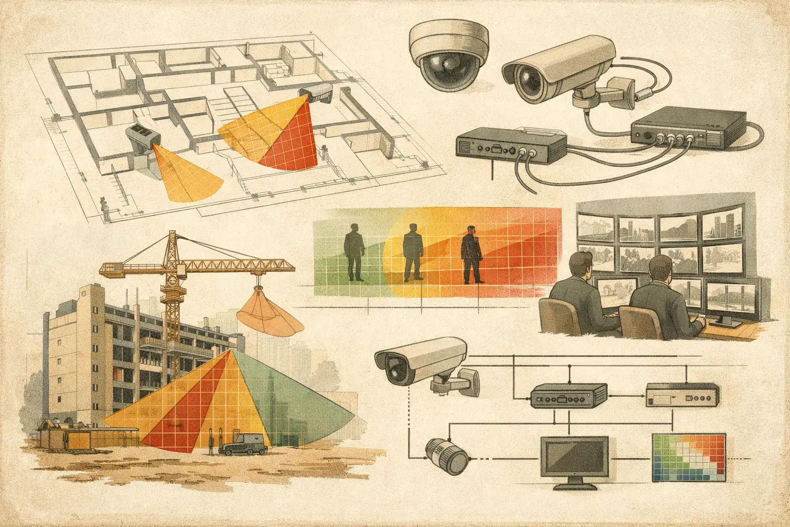
A construction surveillance example is most useful when it shows the design decisions behind the camera symbols, not merely a plan covered in viewing cones. On an active construction site, the perimeter, access routes, material storage, temporary offices, and work zones change frequently. A workable CCTV design therefore needs traceable inputs, calculated coverage, and a review process that can absorb revisions without losing the underlying engineering logic.
This example uses a mid-sized commercial construction site with a temporary perimeter, one vehicle gate, one pedestrian gate, a site office compound, equipment storage, and a partially completed building structure. The objective is to support site security and operational oversight through a documented camera layout. It is not a claim of regulatory compliance or a substitute for a site-specific security assessment.
Construction Surveillance Example: Defining the Site Objective
The first decision is not camera quantity. It is what each camera must achieve at each monitored location. A wide overview image may be appropriate for observing vehicle movement and general activity, while the pedestrian entrance may require enough pixel density to support identification according to the project's stated requirements.
For this example, the security team defines four coverage objectives:
- Observe vehicle entry, exit, and queuing at the main gate.
- Identify people entering through the pedestrian gate.
- Monitor the equipment and material laydown area for unauthorized access.
- Provide general situational awareness around the office compound and the unfinished building perimeter.
These objectives create different DORI and pixel density requirements. Detection, observation, recognition, and identification are distinct operational targets. Specifying a camera with a high resolution does not by itself establish that a target will meet the required PPM at its expected distance. Focal length, sensor size, scene width, mounting position, and target range all affect the calculation.
Establish the design inputs
The design team starts with the latest site logistics drawing, ideally issued with dimensions or another reliable reference measurement. The drawing is imported and scale calibrated against a known distance, such as a verified 50-foot boundary segment. Calibration should be checked against a second known dimension before camera positions are treated as engineering inputs.
The team then records the current physical conditions: fence lines, gates, cabins, stacked materials, lighting towers, parked plant, and the building footprint. The unfinished structure is especially significant because concrete cores, columns, temporary hoarding, scaffolding, and future façade elements can all produce occlusion. A clean two-dimensional drawing that omits these features can overstate usable coverage.
At this stage, it is also useful to identify what will change. For example, the material laydown area may relocate after structural steel delivery, and a vehicle gate may move as roadworks progress. The camera design should distinguish between fixed long-term infrastructure and temporary cameras or poles that can be relocated as the site evolves.
Camera Placement and Coverage Calculations
The main vehicle gate is the highest-priority access point in this construction surveillance example. Rather than relying on a single camera aimed broadly across the entrance, the team uses two design roles: an overview camera and a targeted gate camera.
The overview camera is mounted on a temporary pole set back from the gate line. Its field of view covers approaching vehicles, barrier operation, and the area immediately inside the perimeter. It is configured with a relatively wide horizontal field of view, suitable for observation rather than detailed identification at the far edge of the scene.
The targeted gate camera is aimed at the vehicle approach lane, where the expected target distance and lane width are known. Its focal length and sensor size are selected to achieve the required pixel density across the defined capture zone. The design should show the calculated PPM at the relevant distance, rather than applying a single PPM figure across the whole cone. If the required target area is wider than the calculated field of view, the designer may need a second camera, a narrower capture zone, or a different mounting position.
Treat the pedestrian gate as a controlled target area
The pedestrian gate is designed around a more tightly defined target zone. The camera is mounted at a practical height that balances tamper resistance with viewing angle. Excessive mounting height can create a steep tilt and poor face capture, particularly where workers wear helmets, caps, or high-visibility clothing that creates contrast challenges.
A camera placed closer to the gate and aimed across a narrow passage often provides more predictable pixel density than a high-mounted camera attempting to cover the entire entry forecourt. However, closer placement may increase vandalism risk and require more careful cable protection. The correct choice depends on the site risk assessment, expected traffic flow, available mounting structures, and maintenance access.
Design the laydown area for usable overlap
The equipment and material laydown area presents a different challenge. It is usually open when first planned, then gradually filled with containers, pallets, machinery, and temporary structures. One camera with a wide field of view can provide useful general observation, but stored materials can create blind spots that were not visible in the original plan.
In this case, two cameras are positioned from different sides of the yard. Their fields of view overlap across the central storage zone, while each camera also observes the opposite fence line. The overlap is intentional. It improves situational context and can reduce the chance that a stack of materials blocks all views of an access path.
Coverage overlap is not automatically better everywhere. Too much duplication can add cost, storage demand, switch ports, and review complexity without improving the stated objective. The design should justify overlap where it protects a critical route, covers likely occlusion, or provides a second viewing angle for an incident area.
Model Occlusion Before Installation
A cone drawn through a building wall is not coverage. The site model must account for walls, cabins, containers, and other physical geometry that blocks the line of sight. In the unfinished building zone, the design team adds the concrete core, external columns, temporary site cabins, and access hoarding to the workspace before reviewing each field of view.
One camera initially intended to observe the rear façade appears adequate on the unedited plan. Once the core wall and a container are modeled, a substantial blind spot becomes visible along the rear access route. The response is not necessarily to add another camera. Moving the existing camera to a corner pole and adjusting its direction may restore visibility while reducing the required cable run.
This is why calculated design results should be reviewed alongside actual site conditions. Field verification remains necessary. Temporary plant, elevated work platforms, and newly erected structural elements can introduce occlusion after the design has been issued.
Coordinate Power, Network, and Recording Early
A construction-site CCTV layout can fail operationally even when camera coverage is well designed. The network topology, power source, communications path, and recording assumptions must be coordinated before installation.
For this example, cameras at the office compound connect to a local PoE switch within a secure cabinet. Gate and perimeter cameras use weather-protected field enclosures connected through suitable cable routes or an approved wireless bridge where trenching is impractical. The design records each camera's connection method, estimated cable path, switch allocation, and upstream network route.
Bandwidth and storage calculations should use the proposed camera settings, including resolution, frame rate, codec, and expected retention policy. Actual bandwidth can vary with scene activity, compression settings, lighting conditions, and manufacturer implementation. These figures should therefore be treated as design estimates until validated during commissioning.
Temporary sites also need a practical resilience discussion. If the office compound loses power, determine whether cameras, network equipment, and recording remain available through an appropriately specified backup arrangement. The answer may differ between a theft-prone perimeter gate and a low-priority general observation camera.
Produce a Revision-Ready Deliverable
The final output should allow an installer, consultant, project owner, or reviewer to understand what was designed and why. A professional package typically includes the calibrated plan, camera schedule, mounting heights, directions, tilt, focal length assumptions, field-of-view views, DORI or PPM analysis, blind-spot observations, network topology, and design notes.
It should also state limitations. For example, coverage around the northeast laydown area may be subject to future material stacks, and the gate identification zone may require final adjustment after the barrier and pedestrian route are installed. This is not a weakness in the documentation. It gives the project team a controlled basis for inspection and change management.
A browser-based workspace such as CCTV Design Tool Online can keep the plan, physical geometry, camera parameters, coverage analysis, and report outputs connected as the construction program changes. The result is easier to review than disconnected marked-up drawings, calculation sheets, and manually maintained camera schedules.
The practical value of this construction surveillance example is not that it prescribes one camera layout for every site. It demonstrates a repeatable method: calibrate the drawing, define operational targets, calculate field of view and pixel density, model occlusion, coordinate the network, and document assumptions for review. As the site changes, revise the design from those same controlled inputs rather than starting from a sketch each time.