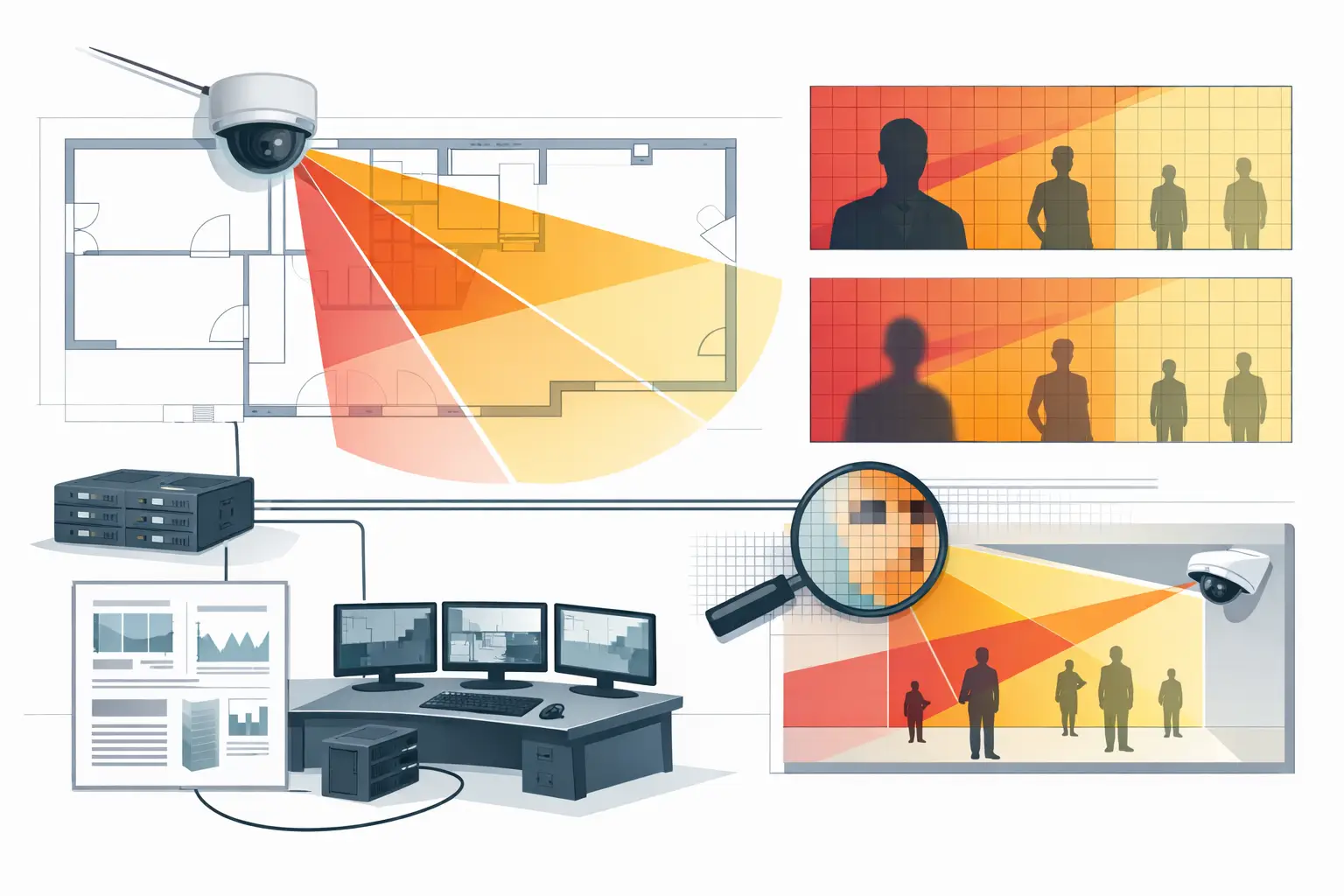
A camera cone reaching the end of a parking lane or lobby does not prove that the video will be usable for the intended task. DORI calculation CCTV work converts that visual assumption into measurable pixel density at a defined target distance. It helps the design team answer a more useful question: can this camera detect activity, observe behavior, recognize a known person, or identify an unknown person at the point that matters?
For consultants, installers, and reviewers, DORI is most valuable when it is treated as part of the design workflow rather than a number added to a camera schedule at the end. The calculation depends on the selected camera, lens, scene geometry, calibrated drawing scale, and the required operational outcome.
What DORI means in CCTV design
DORI describes four increasing levels of usable detail: Detect, Observe, Recognize, and Identify. The concept is commonly expressed through pixel density in pixels per meter or pixels per foot. In many project specifications, the reference values associated with IEC 62676-4 are 25 PPM for detection, 63 PPM for observation, 125 PPM for recognition, and 250 PPM for identification.
These values are a useful engineering reference, not a substitute for a project brief. A site may require identification at an entrance, recognition at a reception desk, and detection only along a perimeter. The relevant standard edition, contract specification, local authority criteria, and customer operating procedures should be verified by qualified project professionals.
The four levels are often misunderstood. Detection indicates that a person or object is present. Observation supports monitoring of general activity and behavior. Recognition supports distinguishing a person known to the operator from others. Identification requires sufficient detail to distinguish an unknown individual with a higher degree of confidence. A wide overview camera can be effective for detection while being unsuitable for identifying a face at the far end of its field of view.
The core DORI calculation CCTV formula
At its simplest, pixel density is calculated as:
Pixel density (PPM) = horizontal camera resolution / horizontal scene width in meters
A 4K camera with 3,840 horizontal pixels covering a scene width of 15.36 meters produces 250 PPM at that plane. That may support an identification design target, assuming the target is correctly positioned, focused, illuminated, and not materially affected by compression, motion blur, or occlusion.
The formula is straightforward. Establishing a valid scene width is where design judgment matters. Horizontal coverage changes with focal length, sensor size, camera direction, mounting position, and distance to the target plane. A floor plan must also be accurately scale-calibrated. If the drawing scale is wrong, every calculated field of view, DORI distance, wall intersection, and coverage result derived from it may be wrong.
For a fixed lens camera, a practical workflow starts with the manufacturer’s verified technical parameters: horizontal resolution, sensor size or active sensor width, focal length, and stated lens characteristics. The camera field of view is then projected onto the plan or model geometry. At each relevant target distance, the system calculates the width covered by the image and converts that width into PPM.
Start with the security task, not the camera resolution
A common design error is selecting a high-resolution camera first and assigning it to every area. Resolution improves the available pixel count, but it does not determine whether the camera is positioned correctly for the task.
Define the target area before selecting the lens. For example, a loading dock may need observation across the full operating area and recognition at the driver access point. A door may need identification across a controlled crossing zone, not throughout the entire corridor. A campus perimeter may require detection along the fence line, with separate cameras covering gates and other decision points at higher pixel density.
This approach prevents an unrealistic expectation that one wide-angle camera can satisfy every DORI level across a large scene. Where a broad overview and a close-detail view are both required, two cameras with different fields of view may be more defensible than one compromised position.
Define the target plane and direction of travel
DORI should be assessed where the subject is expected to appear, not only at the farthest visible point in the camera cone. On a plan, this could be a doorway threshold, cashier position, vehicle lane, pedestrian path, or fence line.
Direction matters as well. A camera may calculate sufficient PPM at a doorway but deliver weak practical identification if subjects approach with faces turned away, strong backlight is present, or the camera angle is too steep. The calculation establishes geometric potential. It does not fully predict the quality of a face, license plate, or other evidential detail in live conditions.
Convert lens and sensor choices into usable coverage
Focal length and sensor size determine how much of the scene reaches the image sensor. A shorter focal length generally creates a wider field of view, spreading the available pixels across more scene width and reducing pixel density at distance. A longer focal length narrows the view, increasing density over a smaller area.
That trade-off must be visible in the design. If a 2.8 mm lens covers an entire lobby but provides recognition only near the camera, it may still be the correct overview camera. It should not, however, be documented as an identification camera for the far entrance without a calculation at that target location.
Varifocal cameras can provide flexibility during commissioning, but a design should record the assumed focal length or focal-length range. If an installer changes the zoom setting in the field, the field of view and DORI coverage change with it. A camera schedule that only states “varifocal” leaves reviewers unable to verify the intended result.
Mounting height and tilt also change the practical design. High mounting can reduce tampering risk and provide broad situational coverage, but it may increase vertical viewing angle and reduce useful facial detail. Low mounting may improve target framing while increasing vulnerability and creating more frequent occlusion by people, shelving, vehicles, or landscaping. There is no universal mounting height. The correct choice depends on the target task, architectural constraints, and maintenance access.
Test geometry before accepting the result
A mathematically correct DORI result can still be operationally misleading if the design ignores physical geometry. Walls, doors, partitions, columns, racking, gates, parked vehicles, and changes in elevation can block the line of sight. A field-of-view overlay that passes through a wall is not coverage.
Review each camera against the actual environment. Confirm whether a wall is solid, whether an opening is permanent, and whether the target zone remains visible when doors are open or closed. Identify blind spots at corners and behind obstructions. Then inspect coverage overlap, particularly at transitions between cameras. Overlap can support continuous tracking, but excessive overlap may consume camera budget without improving the required DORI outcome.
Outdoor scenes need additional caution. Trees, seasonal vegetation, headlight glare, rain, dust, low light, and vehicle movement can materially affect actual performance. Likewise, image compression, frame rate, shutter settings, focus accuracy, and video management system configuration can reduce usable detail even when the plan-level PPM calculation appears sufficient.
Document assumptions so the design can be reviewed
A defensible DORI review should make its assumptions visible. For each camera, record the model or technical parameters used, sensor size, resolution, focal length, mounting height, tilt, direction, target zone, target distance, required DORI level, and calculated PPM. State whether the value is measured at a line, zone, or point on the drawing.
This creates traceability when the architecture changes, a camera is relocated, or a substitute model is proposed. It also gives installers a clear commissioning reference. If the planned lens setting is adjusted, the revised field of view and DORI result can be checked rather than assumed.
A browser-based workspace such as CCTV Design Tool Online can bring these inputs together in one reviewable design: calibrated floor plans, camera parameters, physical walls, field-of-view visualization, DORI coverage, blind spots, overlap, and structured reporting. The calculation remains dependent on the accuracy of the inputs and should be reviewed against the final site conditions.
Use DORI as a decision tool, not a label
The most useful DORI calculation is not the one that produces the largest coverage area. It is the one that ties a defined security task to a verifiable camera position and a documented pixel-density result. When a drawing changes or an installer asks why a longer lens is required at one door but not another, the answer should be visible in the geometry and the target requirement.
That discipline turns camera placement from a visual approximation into an engineering decision that can be reviewed, coordinated, and refined before equipment reaches the site.