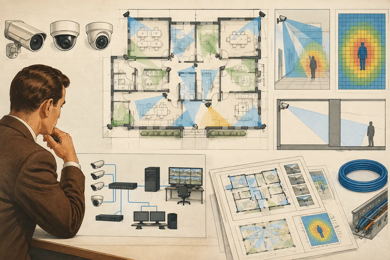
A CCTV layout is not yet a design deliverable simply because cameras appear on a floor plan. Essential CCTV design deliverables must show what each camera is intended to achieve, the assumptions behind its coverage, how it connects to the system, and what an installer and reviewer need to verify before work begins. Without that traceability, a drawing can look complete while leaving critical questions unanswered at procurement, installation, and commissioning.
For consultants, integrators, and project owners, the objective is not to produce more documents. It is to produce a coordinated set of records that lets every stakeholder work from the same design intent. The exact package depends on project scope, contractual requirements, and local authority processes, but several deliverables form the practical engineering baseline.
Start With a Defined Design Basis
Before placing a camera, document the design basis. This is the reference point that explains why a particular field of view, camera type, and pixel density target were selected. It should identify the protected areas, operational objectives, environmental constraints, drawing revision, and known limitations.
A lobby overview camera and a camera intended to support identification at an access-controlled door are not interchangeable design cases. The first may prioritize situational awareness and broad coverage. The second may require a narrower field of view and a higher pixel density at the expected subject location. Stating the objective early prevents a common failure: evaluating every camera against the same, undefined expectation.
The design basis should also record assumptions that need confirmation on site, such as finished ceiling heights, mounting surfaces, obstructions, lighting conditions, access equipment, and cable routes. Calculated coverage is based on inputs. If the mounting height or camera position changes during construction, the associated calculations and views should be reviewed rather than carried forward unchanged.
Essential CCTV Design Deliverables for Coordination
A useful package connects spatial information, optical performance, equipment selection, and infrastructure planning. These documents should reference one another using consistent camera identifiers, drawing revisions, and area names.
1. Calibrated camera layout drawings
The camera layout is the primary coordination drawing. It should be built on a correctly imported and scale-calibrated architectural or site plan, with cameras positioned at their proposed mounting locations. Each camera needs a unique identifier that matches the camera schedule and technical report.
The drawing should show direction of view, mounting location, coverage area, and relevant room or zone boundaries. For exterior designs, it should also show gates, perimeter lines, roadways, building faces, and likely approach paths where applicable. A camera cone without scale calibration is only an illustration. A calibrated plan allows reviewers to assess distances, coverage widths, and the relationship between cameras and physical features.
Geometry matters. Walls, partitions, columns, shelving, doors, glazing, and other obstructions can create occlusion. A field-of-view graphic that passes through a solid wall may be visually persuasive but technically misleading. The layout should distinguish between a theoretical field of view and usable visible coverage after physical obstructions are considered.
2. Field-of-view and coverage analysis
Coverage analysis translates the camera layout into measurable design intent. For each camera, document key inputs such as resolution, sensor size, focal length, mounting height, tilt, and orientation. These inputs determine the calculated field of view and pixel density across the scene.
DORI provides a practical language for discussing whether an area is intended for detection, observation, recognition, or identification. PPM, or pixels per meter, can provide the underlying density measurement used to review those objectives. Neither should be treated as a universal guarantee of evidential performance. Lighting, motion, compression settings, lens quality, scene contrast, subject angle, and recorder configuration can affect actual field results.
The coverage deliverable should highlight blind spots and deliberate coverage overlap. Overlap is not automatically wasteful. It can provide resilience at entrances, preserve a subject path as they move between zones, or provide a second view where one camera may be obstructed. Conversely, excessive overlap can indicate that camera count is being used to compensate for poor lens selection or unreviewed geometry.
3. Camera schedule and technical specification record
A camera schedule turns symbols on a plan into an auditable equipment record. At a minimum, it should include the camera ID, location, mounting height, direction, camera form factor, resolution, lens or focal-length range, selected focal length, and intended coverage objective. Where known, record environmental and installation considerations, such as indoor or outdoor placement, enclosure requirements, mounting method, and illuminator assumptions.
Avoid treating a schedule as a catalog of generic descriptions. “4 MP dome camera” does not explain whether a camera can achieve the required view at its installed position. A useful schedule ties the camera specification to the calculated design result. If a proposed model changes after tender, the replacement should be checked against the recorded sensor size, focal length, resolution, and scene requirement rather than assumed equivalent by megapixel count alone.
4. Network and connectivity plan
CCTV design crosses into ICT coordination as soon as cameras need power, network access, recording capacity, or remote viewing. The network plan should identify the intended topology, communications rooms, switch locations, uplink paths, and the connection point for each camera or camera group. It should distinguish between confirmed pathways and routes that remain subject to site survey or contractor coordination.
At design stage, document estimated bandwidth assumptions, PoE requirements, cable media, and any constraints created by distance or outdoor links. These figures should be validated against selected equipment and project network standards during detailed engineering. A camera layout that cannot be practically cabled, powered, or connected to the required network location is not an installable solution.
5. Installation notes and interface requirements
The most valuable notes address work that is easy to miss when teams operate from separate drawings. Examples include required mounting heights, aiming directions, clearance from obstructions, coordination with ceilings or structural elements, cable containment interfaces, and requirements to maintain camera views after tenant fit-out or landscaping.
These notes should remain specific and verifiable. “Install for optimum view” creates ambiguity. “Mount at 10 feet above finished floor level, aimed toward the entry threshold, subject to final site verification” gives the installer a defined target while recognizing that site conditions may require adjustment.
6. Technical report and review record
A structured technical report brings the package together for client, design-team, and internal review. It should state the design scope, input drawings, camera assumptions, coverage findings, identified limitations, and outstanding actions. Include annotated views where they clarify a complex scene, particularly at entrances, corridors, loading areas, perimeters, and large open spaces.
The report is also the right place to separate design guidance from approval claims. A coverage calculation may demonstrate that a modeled camera arrangement reaches a selected pixel-density target at a defined plane. It does not by itself confirm regulatory acceptance, privacy compliance, final lighting performance, or installation quality. Those questions require review against the applicable project requirements by qualified professionals and, where relevant, the responsible authority.
Make Revisions Traceable
CCTV packages often fail during revisions rather than initial design. An architect moves a wall, an access door changes location, a ceiling drops, or an ICT room is relocated. If the camera layout, schedule, coverage analysis, and network plan are maintained separately, one update can leave the package internally inconsistent.
Use a controlled revision process. Record the plan revision used for design, update affected camera IDs and calculations, and identify whether the change affects coverage, occlusion, cable route, switch capacity, or mounting height. Reviewers should be able to see what changed and why, not reconstruct the decision from scattered email comments.
A persistent design workspace can reduce this coordination burden by keeping calibrated plans, physical geometry, camera parameters, field-of-view calculations, and report outputs together. CCTV Design Tool Online supports that workflow by allowing teams to model camera placement, review DORI and pixel-density coverage, identify blind spots, plan connectivity, and generate structured documentation from the same design record. The results still require engineering review, particularly when construction conditions differ from the modeled environment.
Deliverables Should Support Site Decisions
The best test of a CCTV design package is straightforward: can a reviewer understand the intended outcome, and can an installer translate it into a field installation without inventing missing engineering decisions? If the answer depends on verbal explanations from the original designer, the deliverables need more work.
Clear documentation does not eliminate site verification. It gives that verification a disciplined starting point. When mounting heights, focal lengths, occlusions, pixel-density targets, and network assumptions are visible in one coordinated record, project teams can resolve differences before they become costly changes on site.