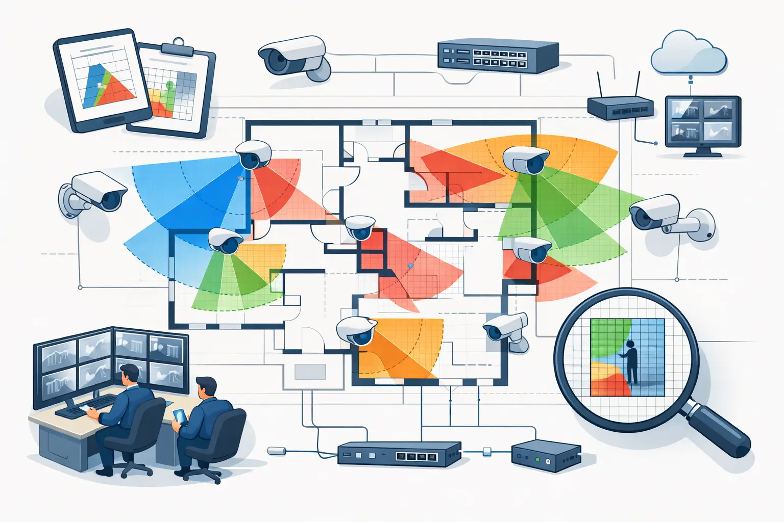
A CCTV drawing can look coordinated and still fail the engineering review. A camera symbol may sit in the right corridor, for example, while the floor plan is out of scale, a new partition blocks the view, or the camera's stated purpose requires more pixel density than the selected lens can provide. A disciplined floor plan markup review turns comments on a drawing into verified design inputs before they become installation changes.
For security consultants, installers, architects, and project owners, the review is not simply an approval step. It is the point at which the security intent, physical environment, camera geometry, and technical documentation are tested against one another. The output should be a traceable set of decisions: what changed, why it changed, who must respond, and what must be recalculated.
What a Floor Plan Markup Review Should Confirm
A useful markup review starts with the premise that not all marks have equal engineering weight. A note saying “add camera” is an instruction to investigate, not evidence that a camera can achieve the required result from the marked location. Likewise, a redline moving a camera several feet may alter the field of view, occlusions, cable route, mounting method, and coverage overlap.
The review should establish whether the drawing is suitable as a design base, whether the camera intent is clear, and whether each markup has consequences for the associated schedule, coverage analysis, and network plan. This is particularly important when security layouts are circulated alongside architectural, electrical, ICT, and fire-life-safety drawings that may be progressing at different revision levels.
At a minimum, reviewers should be able to distinguish between existing conditions, proposed construction, demolition, and items still subject to coordination. A camera cone drawn across a future glazed partition or a newly enclosed lobby is not a minor drafting issue. It changes the calculated usable view.
Start with drawing control and scale calibration
Confirm the drawing title, revision, date, level, and source before reviewing any camera location. If a plan has been exported from a PDF, scanned, cropped, or scaled for presentation, its dimensions may not be reliable by default. Use a known dimension, such as a documented grid spacing or wall length, to calibrate the plan scale.
Scale calibration affects every distance-based result. Mounting distances, scene width, focal-length selection, pixel density, DORI assessment, and cable estimates all depend on it. A plan that is only slightly mis-scaled can produce a confident-looking coverage view with materially incorrect PPM values.
Where dimensions conflict, record the issue rather than selecting the most convenient measurement. The correct response may be a request for the current architectural background. Calculated design results are only as dependable as the geometry and dimensions used to generate them.
Separate comments by their technical effect
Markup clouds often combine several types of feedback: operational requests, coordination notes, architectural changes, and drafting corrections. Treating all comments as visual edits makes it easy to miss a design dependency.
A request to observe a doorway may require a different camera direction. A request to identify a person at that doorway may require a defined pixel-density target and a closer or narrower field of view. A note to relocate a camera due to ceiling coordination may require confirmation of mounting height, tilt, sightlines, network connectivity, and access for maintenance.
Assign each comment to a status such as accepted, rejected with reason, requires information, or requires discipline coordination. That simple distinction prevents unresolved assumptions from being carried into later drawing issues.
Review Camera Intent Before Reviewing Camera Symbols
The most productive question in a markup session is not “Is there a camera here?” It is “What must this camera accomplish?” A general overview of a loading area, recognition at a vehicle entrance, and identification at an access-controlled door are different design tasks. They may need different camera positions, focal lengths, resolutions, or coverage zones.
For each marked camera, confirm the operational purpose, target area, required observation level, and any important direction of movement. Then test the camera specification against that purpose. Resolution alone is not a coverage result. Sensor size, focal length, mounting height, direction, tilt, and scene distance all influence the pixels available on the target.
DORI and pixel-density calculations provide a disciplined way to review this relationship. They help indicate whether a scene supports detection, observation, recognition, or identification at the relevant distance. However, they remain calculated outputs. Actual field performance can also be affected by lighting, motion, compression, scene contrast, installation tolerances, lens quality, and device-specific analytics behavior.
Check the field of view against physical geometry
Camera cones should not pass through walls, shelving, columns, doors, or other permanent obstructions. Reviewers should verify wall geometry and openings before treating a field-of-view visualization as meaningful. This is especially relevant in office fit-outs, retail spaces, warehouses, and transport facilities, where late architectural changes can introduce significant occlusion.
Do not assume an open door remains open, or that a glazed partition has no effect on the operational scene. Reflections, access-control queues, signage, and furniture can reduce the practical value of an otherwise valid geometric view. Where an item is movable or uncertain, flag it as an operational risk rather than modeling it as a fixed certainty.
Coverage overlap deserves the same scrutiny. Overlap can support continuity and reduce blind spots at transitions, but excessive overlap may consume camera count without improving the required observation task. The appropriate amount depends on risk, operational workflow, incident investigation needs, and the consequences of losing a single view.
Turn Redlines Into a Controlled Revision Workflow
A reviewed markup should create a controlled next action, not a collection of annotations that must be interpreted again later. The best workflow connects each accepted change to the affected design elements.
If a camera is added, update its identifier, location, direction, technical parameters, coverage calculations, network endpoint, power approach where applicable, and report content. If a wall moves, reassess every affected camera rather than only the nearest symbol. If the intended use changes from overview to identification, revisit the optical design rather than merely changing a note in the schedule.
This is where a persistent design workspace is more reliable than a disconnected sequence of PDFs, screenshots, spreadsheets, and manually edited reports. In CCTV Design Tool Online, a team can import and calibrate the floor plan, model walls, position cameras, review field of view and DORI, and maintain the associated technical output in one design environment. The engineering judgment still belongs to the reviewer, but the relationship between a change and its design consequences is easier to trace.
Coordinate installation and network implications
A markup review is also an early constructability check. The preferred viewing position may conflict with a ceiling feature, access hatch, façade detail, lighting fixture, or safe maintenance route. These issues should be identified before a location becomes fixed in procurement or installation documentation.
Network topology deserves attention whenever the layout changes. Camera relocation can alter cable pathways, copper distance assumptions, cabinet assignments, switch-port allocation, and resilience planning. A camera added late to a remote building zone may appear simple on the floor plan while requiring a new pathway, local switch capacity, or a revised fiber strategy.
The review does not replace coordination with electrical, ICT, architectural, and construction teams. It gives those discussions a more precise technical basis. Record dependencies clearly, especially where information is pending from another discipline.
A Practical Review Sequence for Project Teams
Begin with the latest controlled architectural background and confirm scale calibration. Next, review proposed walls, openings, ceiling conditions, and known obstructions. Then assess every camera against its operational purpose, field of view, mounting height, tilt, and required pixel density.
After the visual and optical review, check coverage continuity, blind spots, and overlap at entrances, corridors, perimeter transitions, and other risk areas. Finally, carry approved changes through the camera schedule, network planning assumptions, and report set. A second reviewer should be able to understand the outcome without interpreting informal markups from scratch.
It is reasonable for some items to remain open. Early design phases may not yet confirm final furniture, ceiling heights, or tenant layouts. The key is to state what has been assumed, what requires verification, and what recalculation will be needed when the information arrives. This preserves design traceability without overstating certainty.
Make the Review Useful at Site Level
The final issue should communicate more than camera dots and arrows. It should show decision-ready information: controlled drawing references, camera IDs, intended coverage areas, relevant mounting assumptions, unresolved coordination items, and the basis for calculated coverage results. Installers need enough information to set out the system correctly; project managers need visibility of dependencies; reviewers need to see that comments were closed with evidence.
A floor plan markup review is most valuable when it reduces ambiguity before work reaches the ceiling, wall, or equipment room. Treat every redline as a potential change to geometry, optics, infrastructure, and documentation, and the review becomes a practical engineering control rather than a final drawing exercise.