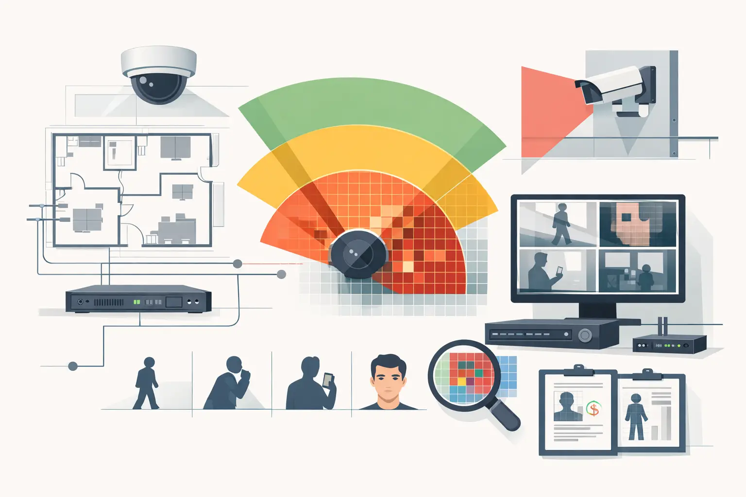
A camera can show a doorway clearly on a coverage drawing and still deliver too few pixels across a face, vehicle plate area, or transaction point. That gap is why learning how to assess pixel density is more useful than relying on a camera cone, a megapixel figure, or a broad statement that an area is “covered.”
Pixel density turns an operational requirement into a measurable design input. It connects camera resolution, lens selection, field of view, target distance, and scene geometry to the detail available at the point where an event must be reviewed.
How to assess pixel density from the operational task
Start with the question the camera must answer. “Monitor the lobby” is a coverage objective, not a measurable image requirement. A more useful brief states what the operator, investigator, or recording must support: detect activity at an entrance, observe movement around a perimeter, recognize a known person at a reception desk, or identify an unknown person at a controlled doorway.
DORI provides a practical vocabulary for this discussion: Detection, Observation, Recognition, and Identification. It helps distinguish between seeing that something is present and obtaining enough image detail to make a reliable decision about what or who is present. The required level should be agreed for each target area, not assigned uniformly across an entire project.
Published DORI pixel-density values can be useful reference points, but they are not a substitute for a project brief, site conditions, or a qualified review. A pixel-density calculation describes the spatial sampling available in the modeled scene. Actual evidential usefulness also depends on lighting, motion blur, compression, focus, exposure settings, camera angle, and the subject’s behavior.
Calculate pixels per foot at the target plane
In CCTV design, pixel density is commonly expressed as pixels per foot (PPF) in US projects or pixels per meter (PPM) in many international specifications. The principle is the same:
Pixel density = horizontal image pixels / real-world width covered at the target distance
For example, a camera producing 3840 horizontal pixels views a 24-foot-wide section of wall at the target plane. Its calculated density at that distance is 160 PPF. If the same camera and lens view expands to 48 feet wide farther from the camera, density falls to 80 PPF.
This is the essential trade-off. Resolution adds pixels, but focal length controls how those pixels are distributed across the scene. A wide lens can give useful situational coverage while spreading available pixels over a larger width. A longer focal length narrows the field of view and increases pixel density at the target, but may create blind spots beside or in front of the camera.
Use the delivered horizontal resolution, not only the camera’s marketing megapixel count. A camera may support multiple streams, crops, dewarping modes, or recording settings. If the recorded stream has a lower horizontal pixel count than the sensor’s maximum mode, base the design check on the recording configuration that will actually be used.
Measure at the plane that matters
The target plane is the location where detail is required. For a doorway, that may be a vertical plane through the normal walking path. For a loading yard, it may be the vehicle route. For a fence line, it may be a series of points along the perimeter rather than the open ground in front of it.
Do not use the camera-to-subject distance alone as a shortcut. The relevant measurement is the real-world scene width represented by the image at that exact plane. With an angled camera, a tilted view, or a corridor that recedes from the lens, field-of-view width changes across the scene. Pixel density should therefore be checked at multiple critical locations when the protected area extends in depth.
A plan view is valuable for locating these checks, but elevation and three-dimensional geometry matter as well. Mounting height and tilt affect perspective, facial angle, occlusion, and the area visible near the camera. A mathematically sufficient PPF figure at a distant wall does not correct a poor angle at the doorway where a person’s face is expected to be captured.
Use camera inputs that reflect the real design
A defensible assessment begins with traceable inputs. Confirm the camera’s horizontal resolution, sensor size, focal length or varifocal setting, mounting height, direction, tilt, and intended target areas. Sensor size and focal length together determine the optical field of view. Changing either one changes the width of scene represented by the image.
For varifocal cameras, assess the selected focal length rather than the full lens range. “2.8 to 12 mm” does not describe a field of view until a design setting is chosen. If field adjustment will be performed during commissioning, define an acceptable focal-length range and recheck the resulting coverage after the final setting is recorded.
The floor plan must also be scale calibrated correctly. An error in drawing scale changes measured distances and widths, which then changes pixel-density outputs. Before using results for specification or approval review, validate the calibration against a known site dimension, such as a structural grid, measured corridor width, or surveyed boundary.
Check coverage, occlusion, and overlap together
Pixel density is only one part of camera suitability. A high-density zone hidden by a partition, racking, landscaping, a door swing, or a vehicle is not useful coverage. Review walls, openings, fixed equipment, and likely temporary obstructions against each critical line of sight.
Likewise, a single wide camera may meet a lower detection objective across an open area but be unsuitable for recognition at its far edge. This is often resolved by separating situational coverage from detail coverage: one camera maintains broad awareness while another is aimed and configured for the higher-density target zone.
Coverage overlap deserves a deliberate review. Overlap can provide continuity when a person moves between cameras, reduce the effect of localized occlusion, and support different viewing angles. Too much overlap, however, can consume camera, storage, and network capacity without improving the required task. The design question is whether each overlapping field of view contributes a defined operational purpose.
Validate results on the drawing before installation
A repeatable workflow reduces assumptions and makes design decisions easier to review:
- Import and calibrate the drawing against verified dimensions.
- Add walls, openings, level changes, and significant obstructions that affect line of sight.
- Place cameras using their intended mounting locations, height, direction, tilt, resolution, sensor size, and focal length.
- Define target planes and required DORI or PPF/PPM criteria for entrances, circulation routes, transaction points, perimeter segments, and other critical areas.
- Review pixel-density coverage at the target planes, then inspect blind spots, occlusion, and unnecessary overlap.
- Record assumptions, selected camera settings, and unresolved site dependencies in the technical deliverable.
A browser-based design workspace such as CCTV Design Tool Online can bring these geometry, field-of-view, DORI, and pixel-density checks into one model rather than splitting them among scaled drawings, manual calculations, and separate reports. The output should still be reviewed against verified site conditions and the final camera datasheet.
Account for factors pixel density does not solve
Pixel density measures potential scene detail, not final image quality. A camera pointed toward strong backlight may produce a lower-value image than its calculated density suggests. Low-light noise, aggressive compression, insufficient shutter speed, focus errors, dirty housings, and poorly positioned infrared illumination can all reduce practical performance.
Perspective is especially relevant for recognition and identification tasks. A high camera mounted steeply above a doorway may view mostly the top of a person’s head. Increasing focal length may raise PPF at the threshold while leaving the viewing angle unsuitable. Where facial detail is required, assess the expected direction of travel, face angle, mounting height, and lighting as part of the same design decision.
Network and storage settings should also match the intended outcome. If a design uses high-resolution cameras to achieve a target density but later reduces frame rate, bitrate, or recording quality without review, recorded performance may not match the design basis. Coordinate the camera schedule with network topology, bandwidth assumptions, recording retention, and VMS configuration.
Document the decision, not just the number
A useful report does more than label a zone with PPF or PPM. It identifies the target, required task, camera configuration, calculated result, field-of-view limits, and relevant assumptions. It should make clear whether a result is a design calculation or a site-verified observation.
Where a project is subject to authority, client, insurer, or jurisdiction-specific requirements, confirm the applicable criteria with the responsible qualified professional and relevant reviewing body. A pixel-density map supports engineering review, but it does not independently establish compliance or guarantee installed performance.
The most reliable pixel-density assessment is one that remains understandable months later: another reviewer can see what had to be achieved, where it had to be achieved, which camera settings were assumed, and what must be verified during commissioning. That traceability is what turns a coverage drawing into a practical CCTV design decision.