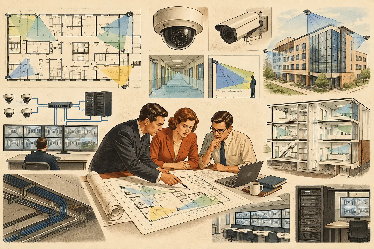
A camera location can be correct on a security drawing and still fail as an installation decision. The cable route may be blocked by structure, the nearest telecom room may exceed the planned channel length, a door may occlude the view, or the PoE switch may have insufficient power budget. Knowing how to coordinate CCTV ICT means resolving these dependencies before they become site instructions, variations, or coverage compromises.
For most building projects, CCTV coordination is not a single meeting between a security contractor and an ICT contractor. It is a controlled workflow that connects operational requirements, camera geometry, architectural constraints, containment routes, network topology, power, and final documentation. The goal is traceability: every camera should have a purpose, a physical position, a viable connection path, and an identifiable network endpoint.
Start With a Shared Design Basis
Coordination begins before camera symbols are placed on a plan. The security designer, ICT designer, architect, and project team need a common design basis that defines what the system is expected to achieve. “Cover the lobby” is not sufficient. The team should establish whether the camera is intended for overview monitoring, observation, recognition, or identification, then translate that requirement into a target pixel density or DORI objective at the relevant distance.
This distinction affects nearly every downstream decision. A wide-angle camera may provide useful situational awareness across a lobby but may not achieve recognition at a reception desk several meters away. A tighter focal length can improve pixel density at the target but reduces the field of view and may introduce blind spots. Camera selection and placement must therefore be reviewed as an optical and operational decision, not merely an ICT point on a drawing.
At this stage, align the current architectural plan revision, reflected ceiling plan, elevations, room data, and telecom room locations. Confirm the drawing scale before coverage is assessed. An uncalibrated floor plan can make a field-of-view calculation appear credible while placing distances, PPM, cable routing, and camera spacing on the wrong basis.
Coordinate CCTV ICT Through the Physical Model
The most common coordination failure is treating a camera cone as if it can pass through walls, glazing, doors, columns, bulkheads, or racking. A field-of-view diagram must be tested against real physical geometry. Mounting height, camera direction, tilt, sensor size, focal length, and resolution all affect calculated coverage, but physical obstructions determine whether that coverage is available in practice.
Validate Each Camera Location
For each camera, review the proposed mount against the ceiling type, wall construction, access requirements, and nearby services. A camera may conflict with an air diffuser, sprinkler head, lighting fixture, signage, or access panel. Relocating it by even a small distance can change the viewing angle, the usable scene depth, and coverage at the target area.
Coordinate the final mounting position with a reference that can be set out on site. A schedule should identify the camera ID, drawing reference, mounting height, mounting surface, orientation, tilt, and intended view. If a camera is wall-mounted, confirm that the wall is structurally and architecturally suitable. If it is ceiling-mounted, verify that the proposed support method is compatible with the ceiling system and that access is available for installation and maintenance.
Camera height is particularly significant. Raising a camera may improve the overview of circulation areas, but it can also increase viewing angles on faces and reduce useful identification performance. Lowering it can improve detail at a doorway while increasing susceptibility to vandalism or obstruction. There is no universal “best” height. The correct choice depends on the operational objective, geometry, and physical environment.
Review Occlusion, Not Just Coverage Extent
Coverage overlap is often necessary at entrances, intersections, loading areas, and handover points between camera zones. However, overlap should be purposeful. Two cameras that both see a wide area at low pixel density may not provide the evidence quality required at a critical target.
Review doors in their open position, shelving or furniture layouts where known, vehicle movements, landscaping, and expected temporary obstructions. For outdoor sites, account for poles, canopies, trees, gates, and changes in ground level. A calculated field of view is a design output, while actual scene performance must still be verified through installation, aiming, lighting conditions, and commissioning tests.
Build the Network Topology From Camera Requirements
Once physical camera positions are stable, develop the ICT design around the actual camera schedule rather than an assumed device count. Each camera requires a defined network connection, cable route, switch port, power source, and logical destination. The topology should show how field cameras connect to local switches, telecom rooms, distribution switches, recording infrastructure, and any relevant management network boundaries.
For IP cameras, estimate bandwidth using the intended resolution, frame rate, compression settings, scene activity, and retention strategy. These values are design assumptions, not fixed manufacturer-independent outcomes. Motion, low-light conditions, codec configuration, analytics, and VMS settings can materially change actual throughput. Document the assumptions and allow the ICT team to validate switch uplinks, storage interfaces, and network segmentation requirements.
PoE planning needs the same discipline. Do not multiply the nominal power of every camera and stop there. Identify the applicable device power requirement, including heaters, IR illumination, PTZ movement, or other accessories where specified. Then coordinate switch PoE capacity, available port count, power supply resilience requirements, UPS strategy, and heat load within the telecom enclosure. A switch may have enough ports while lacking enough usable PoE budget for the connected camera mix.
Align Pathways, Containment, and Cable Limits
A camera position is only installable when there is a practical route from the device to the network point. Coordinate containment routes with electrical, mechanical, architectural, and fire-stopping disciplines early. The preferred route on a drawing may be inaccessible above a finished ceiling, unavailable after structure is installed, or congested by other services.
Identify whether each camera will use structured cabling, fiber, a local cabinet, or another approved project method. Confirm the route length against the applicable cabling design limits and include realistic pathway distance rather than a straight-line measurement. Vertical risers, route diversions, service loops, and transitions between buildings can quickly change the result.
For exterior cameras, coordination should also address cabinet locations, environmental protection, grounding or bonding requirements where applicable to the project, and the transition between external and internal pathways. These details must follow the project specification, local requirements, and qualified engineering review rather than generic assumptions.
Use One Camera Schedule as the Coordination Record
A fragmented schedule is a reliable source of rework. Security drawings may show one camera ID, the ICT port schedule another, and the contractor’s installation list a third. Establish a single controlled camera schedule that is updated with each coordinated revision.
At a minimum, it should connect the camera ID with location, mounting information, key optical parameters, network switch and port reference, cable identifier, estimated route length, PoE requirement, and design status. Where appropriate, add the required pixel density or DORI objective and a note on important scene constraints, such as a door swing or restricted mounting zone.
This record gives each discipline a usable input. The security consultant can review coverage intent, the ICT designer can check ports and uplinks, the installer can trace routes and mounting details, and the project manager can identify unresolved dependencies. It also makes late changes visible. If a ceiling revision moves a camera, the team can assess the effect on field of view, PPM, cable route, containment, and port allocation rather than changing only a symbol on a plan.
Review Coordination at Defined Gates
CCTV and ICT coordination benefits from formal review points rather than continuous informal updates. A concept-stage review should confirm operational areas, camera types, telecom room strategy, and high-risk physical constraints. A detailed-design review should test geometry, blind spots, coverage overlap, containment feasibility, cable routes, switch capacity, and schedule consistency.
Before installation, issue a coordinated package that includes the latest plans, camera schedule, network topology, relevant elevations or mounting details, and clear revision status. During construction, treat site discoveries as controlled changes. If a beam, duct, or ceiling change affects a camera, reassess the optical result and network impact before approving a relocation.
A browser-based workspace such as CCTV Design Tool Online can support this process by keeping calibrated drawings, walls, camera positions, field-of-view calculations, DORI or pixel-density outputs, and report data connected in one project record. It supports engineering review, but it does not replace site verification, qualified design responsibility, or project-specific authority requirements.
Close the Loop During Commissioning
Commissioning should test the coordinated design rather than only confirm that cameras are online. Verify camera IDs against the schedule, physical mounting positions, views, focus, image quality, recording, network connectivity, and power behavior. Test the operational targets that informed the original design, especially entrances, cash handling points, vehicle gates, and other critical areas.
Where field conditions differ from the model, record the change and update the deliverables. The final as-built package should show what was installed, not what was once intended. That discipline gives operations teams a dependable reference for maintenance, expansions, incident review, and future refurbishment work.
Good CCTV ICT coordination is measured by fewer assumptions carried to site. When camera geometry, physical constraints, network capacity, and documentation are reviewed as one system, the project team can make trade-offs early, with evidence, while changes are still manageable.