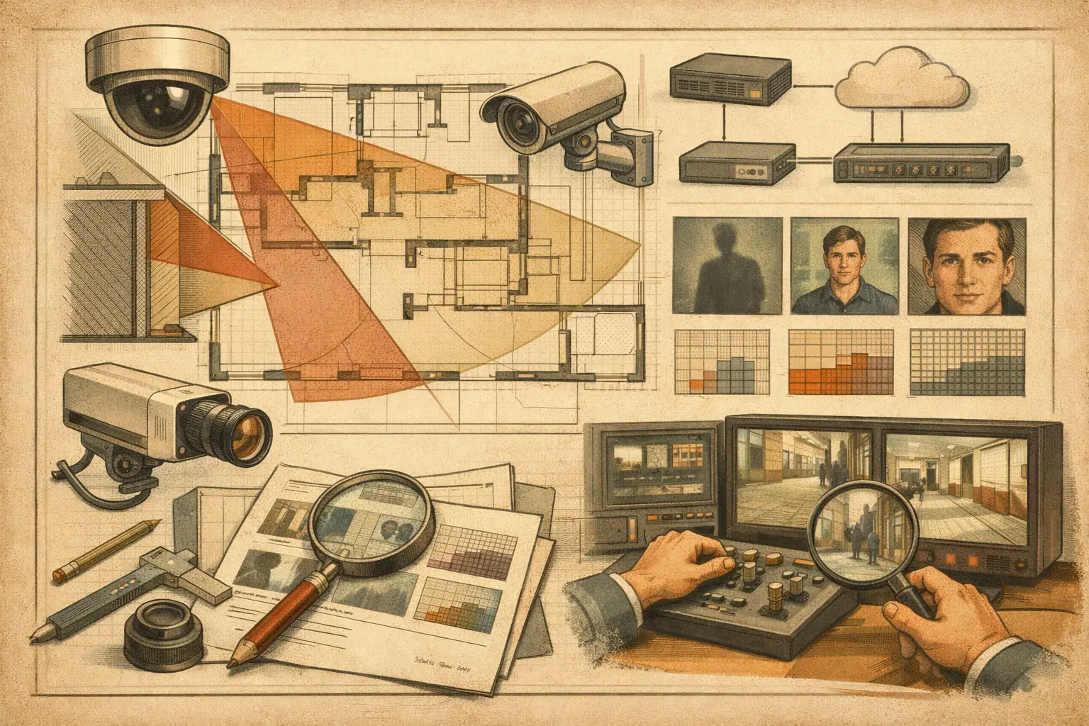
A camera schedule can look technically complete while still failing the design brief. A model may offer high resolution, infrared illumination, and a motorized lens, yet provide insufficient pixel density at the target or create unusable coverage because a wall, canopy, vehicle route, or mounting angle was not considered. To review CCTV camera specifications properly, assess each parameter in relation to the scene, the required task, and the installed geometry.
This is not a product-selection exercise alone. It is an engineering review that connects camera data to field of view, focal length, sensor size, mounting height, tilt, occlusion, recording requirements, and network topology. The output should be a traceable basis for approving, revising, or rejecting a proposed camera configuration.
Start With the Operational Requirement
Before reviewing a datasheet, establish what the camera must achieve at each location. “Monitor the entrance” is not a measurable requirement. A stronger requirement identifies the relevant target area, the viewing direction, the expected subject, and the level of usable image detail needed for the operational task.
For example, a loading-bay overview camera may need broad situational awareness across vehicle movement and pedestrian routes. A camera at an access-controlled door may require sufficient detail over a much narrower zone. These are different design cases, even if both locations receive cameras with the same nominal resolution.
Define the review inputs first: the target distance, target width or area, mounting position, likely lighting conditions, required coverage period, and required pixel density or DORI objective. DORI provides a useful framework for distinguishing detection, observation, recognition, and identification needs, but the project team should define how those categories are to be applied. Calculated DORI results are design indicators, not proof of real-world performance under every lighting, motion, compression, or environmental condition.
Review CCTV Camera Specifications in the Right Order
Reviewing specifications in datasheet order often leads to poor decisions. Resolution is usually listed first, but optics and scene geometry determine whether those pixels are placed where they matter. Review the specification set in an order that reflects the design outcome.
Confirm resolution and usable image dimensions
Resolution establishes the available pixel count. It does not, by itself, establish image detail at a doorway, gate, perimeter line, or vehicle lane. Review both the stated resolution and the active image format used by the proposed stream. A camera capable of a higher maximum resolution may be configured at a lower resolution to reduce bandwidth or storage.
Also check whether the selected stream settings, frame rate, codec, and recording profile preserve the intended design basis. A high-resolution camera running an aggressively constrained secondary stream may not support the required use case. The review should record the assumed operating stream, rather than simply copying the maximum datasheet value into a schedule.
Check sensor size, focal length, and field of view together
Sensor size and focal length work as a system. A 4 mm lens does not produce one universal field of view because the sensor format affects the result. Likewise, a varifocal camera is not automatically suitable for a location until the proposed focal-length setting is defined.
Review the horizontal field of view at the intended focal length and calculate the scene width at the target distance. From there, assess pixel density across the actual target plane. This is more defensible than judging a camera cone by appearance on a drawing.
A wide field of view can improve contextual coverage, but spreads pixels across a larger area. A narrower view increases pixel density at distance but can introduce blind spots at the edges or beside the camera. The appropriate trade-off depends on the operational requirement, not on whether the camera has the widest or narrowest advertised lens range.
Evaluate pixel density at the target, not only at the camera edge
Pixel density, commonly expressed as pixels per meter or PPM, should be reviewed where the target is expected to appear. For a flat wall or access point, this may be straightforward. For roads, corridors, ramps, and open areas, the target distance and viewing angle can vary materially across the field of view.
Use the image width at the relevant distance and divide the available horizontal pixels by that width to establish the calculated PPM. Then compare the result with the project’s stated DORI or operational criteria. Where the target area is oblique to the camera, document that geometry. A person moving across a scene at an angle may present less usable facial or object detail than a simple plan-view calculation suggests.
Do not let a single PPM figure conceal variation. A camera may satisfy the required density at a gate line while falling below it several meters beyond the line. That may be acceptable if the requirement is limited to the gate, but it should be explicit in the review record.
Assess mounting height, tilt, and perspective
Mounting height affects more than vandal resistance and physical access. A high mounting position can improve overview coverage and reduce near-field obstruction, but steeper tilt changes the perspective of faces, objects, and ground-level activity. It can also cause distant targets to occupy fewer useful pixels than expected.
Review the camera direction and tilt against the expected target plane. Check whether signs, overhangs, shelving, parked vehicles, landscaping, lighting poles, or architectural features create occlusion. A field-of-view cone that passes through a wall is not coverage. The drawing should reflect walls, openings, partitions, and physical geometry with a calibrated scale.
For interior scenes, account for door swing, furniture layouts, and likely changes in occupancy. For exterior scenes, consider gates, vehicle queues, seasonal vegetation, and likely construction of fences or canopies. Not every future condition can be modeled, but known constraints should not be ignored because they are inconvenient.
Review Low-Light Claims With Appropriate Caution
Low-light specifications require careful reading. Minimum illumination values, infrared range, wide dynamic range, and image-enhancement features are manufacturer-specific claims measured under defined test conditions. They are useful comparison inputs, but they do not replace a lighting assessment of the actual scene.
Review whether the location contains bright backlighting, headlights, reflective surfaces, rapid lighting transitions, or uneven illumination. A camera facing a glazed entrance during daylight and the same camera observing that entrance after dark represent two distinct operating conditions. Infrared can support viewing in low light, but reflections from glass, nearby surfaces, rain, fog, or insects can affect the usable image.
Where evidential detail is required, record the assumptions about lighting, exposure behavior, shutter settings, frame rate, and motion. Field commissioning should verify these assumptions. The calculated design result and actual installed performance are related, but they are not the same thing.
Include Recording and Network Parameters in the Review
A camera is not fully specified until its video stream can be carried, recorded, and retrieved within the project architecture. Review the expected bitrate range, codec, frame rate, resolution, recording schedule, retention basis, and storage assumptions. Bitrate varies with scene activity, lighting, compression configuration, and image complexity, so a maximum or typical manufacturer value should not be treated as a fixed operational result.
Then review network topology. Identify the switch, uplink, power source, VLAN or segmentation approach where applicable, and the path back to the recording platform. Confirm that PoE budget, port capacity, uplink capacity, and resilience requirements are assessed by the relevant project disciplines. A camera selection that works optically but overwhelms an access switch or storage design is incomplete.
For large sites, camera schedules should carry enough information for security, ICT, electrical, and construction teams to coordinate without recreating assumptions in separate spreadsheets. Camera ID, location, model reference, resolution, lens setting, mounting height, direction, tilt, field of view, PPM or DORI result, and network connection point are useful review fields.
Turn the Review Into a Verifiable Design Record
The strongest specification review is spatial. It links each camera’s technical parameters to a calibrated plan, physical geometry, target areas, coverage overlaps, and blind spots. This makes it easier to identify where two cameras unintentionally duplicate broad overview coverage while a critical doorway remains underdesigned.
A browser-based workspace such as CCTV Design Tool Online can support this review by placing camera parameters, field-of-view calculations, DORI analysis, obstructions, and reporting outputs in the same design record. The value is not automation for its own sake. It is the ability to trace why a particular lens setting, mounting position, and camera count were selected, then revise the design without disconnecting the drawing from the schedule.
Manufacturer datasheets should still be checked against official current documentation, and final equipment selection should be verified by qualified professionals. Project requirements, local authority expectations, privacy obligations, and installation constraints may introduce additional criteria beyond the camera specification review.
A useful closing question for every camera is simple: can the team show, on the drawing and in the schedule, what this camera is expected to achieve at its target area and what assumptions that result depends on? If the answer is clear, the design is ready for a more disciplined review.