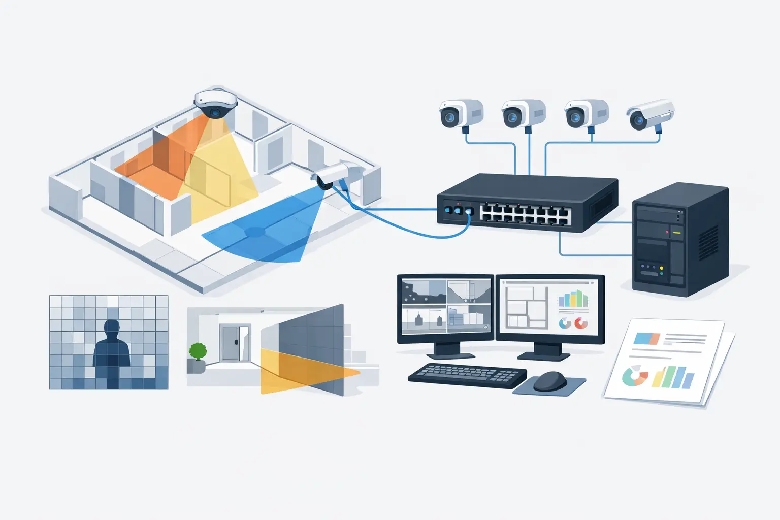
A switch that has enough ports can still be the wrong switch. CCTV network failures commonly emerge at the uplink, in the PoE power budget, or when an assumed camera bitrate changes after commissioning. Knowing how to size CCTV switches means treating the switch as part of the surveillance design, not as a final procurement line item.
The required switch capacity is driven by the camera schedule, field-of-view requirements, recording architecture, cable routes, and network topology. A 4K camera configured for a wide scene, for example, may need a different bitrate and PoE allowance than a lower-resolution camera with a narrower focal length and a different scene complexity. Size the switching layer from verified design inputs, then retain headroom for operational change.
Start with a coordinated camera schedule
Before selecting ports or calculating bandwidth, establish a camera schedule that reflects the intended design rather than a generic device count. For every camera, record the resolution, frame rate, compression codec, target bitrate or bitrate range, power class, mounting location, and connection point.
The camera specification should follow the coverage requirement. Field of view, sensor size, focal length, mounting height, tilt, and required pixel density influence the camera selected for each scene. DORI and PPM calculations help establish whether the proposed view supports observation, recognition, or identification at the required distance. They do not directly determine switch capacity, but they determine the camera settings from which bandwidth and power demand are derived.
A schedule should also identify special loads. PTZ cameras, cameras with heaters or blowers, illuminators, microphones, edge analytics, and multi-sensor units can materially change both PoE demand and bitrate. Do not assume that every camera uses the same power or network load.
How to size CCTV switches from bandwidth
Calculate access-switch bandwidth by adding the expected camera streams connected to that switch. Use the configured or specified bitrate, not resolution alone. Resolution is an incomplete proxy because codec, frame rate, scene motion, low-light noise, wide dynamic range settings, and variable bitrate behavior all affect the result.
For a first engineering calculation:
`Access-switch load = sum of camera bitrates connected to the switch`
If eight cameras are expected to transmit at 6 Mbps each, the nominal camera load is 48 Mbps. That figure may fit comfortably within a 1 Gbps uplink, but the decision is not complete. Consider the traffic direction, whether cameras send one or more streams, whether video is viewed locally, and whether the uplink also carries other services.
Variable bitrate requires particular care. A camera’s average bitrate may look acceptable in a quiet scene, then increase with movement, weather, foliage, crowds, or image noise. Constant bitrate provides a more predictable ceiling but may affect image quality when scene complexity increases. The right approach depends on the project’s recording objectives, storage model, and manufacturer-verified camera settings.
Apply engineering headroom rather than designing an uplink at its expected maximum. The appropriate allowance depends on the project and the certainty of the inputs, but 20% to 30% is a practical starting point for many designs. Higher headroom can be justified where future camera additions, variable bitrates, or shared ICT traffic are expected.
Size uplinks separately from camera ports
A common error is to confirm that each access switch has gigabit ports and stop there. The uplink must carry the aggregate traffic from all cameras downstream, plus any other traffic crossing that path.
If four PoE access switches each carry 300 Mbps of camera traffic, their combined demand can exceed a 1 Gbps aggregation uplink even though each individual access switch is below 1 Gbps. Review every network segment from camera to recorder, VMS server, viewing client, and storage location. The narrowest segment in the route governs practical capacity.
Where the design uses redundant paths, link aggregation, or ring topologies, calculate both normal and failure conditions. Redundancy can preserve connectivity, but a failed path may concentrate traffic onto a remaining uplink. Confirm how the network is intended to behave after a link or switch failure with the ICT team and the equipment documentation.
Calculate the PoE budget, not just the port count
PoE capacity is often the limiting factor on CCTV switches. A 24-port PoE switch may physically connect 24 cameras, yet its total PoE budget may not support them simultaneously.
Start with each camera’s maximum stated power draw from the official datasheet. Use the applicable operating condition, especially for outdoor cameras and devices with integrated illumination, heaters, or PTZ movement. Sum the loads, then add a sensible margin for startup demand, environmental conditions, and future changes.
`Required PoE budget = sum of maximum device power + design allowance`
For example, 16 fixed cameras at 9 W and four PTZ cameras at 28 W produce a stated maximum demand of 256 W. With a 25% allowance, the design target becomes 320 W. A switch with a 250 W PoE budget is therefore unsuitable, regardless of its 24 available ports.
Also verify the PoE standard required by each endpoint. Devices may require IEEE 802.3af, 802.3at, or 802.3bt. A switch port can be gigabit-capable but still fail to provide the required power class. Confirm the power available per port as well as the total switch budget.
Cable length and conductor quality affect delivered power. Ethernet channel limits, installation practices, ambient temperature, and voltage drop should be reviewed by qualified designers and installers. Where long routes or high-power devices are involved, do not rely solely on a simplified PoE spreadsheet calculation.
Choose a topology that matches the site
Switch sizing is inseparable from physical topology. A small office may use one centrally located PoE switch. A campus, warehouse, residential development, or transport environment may need distributed edge switches to keep copper runs within the planned channel length and to reduce containment complexity.
Distributed switching creates additional design questions: cabinet space, UPS runtime, thermal conditions, fiber uplinks, surge protection, access control, and maintenance access. An outdoor or field cabinet may need an industrially rated switch, an appropriate enclosure, and a power strategy suitable for the actual environment. These are project-specific engineering decisions, not automatic product substitutions.
Network segmentation should also be agreed with the client’s ICT requirements. A dedicated CCTV VLAN may simplify traffic management and operational separation, but its addressing, routing, access rules, time synchronization, and VMS connectivity must be coordinated with the wider network design. Cybersecurity requirements vary by organization and jurisdiction, so they should be defined by the responsible project stakeholders.
Check recorder and core-switch capacity
Switch capacity does not end at the camera edge. The recording server, NVR, VMS server, storage network, core switch, and operator workstations must handle the same video flows at the points where those flows converge.
A design may show 500 Mbps from edge switches to the core, then require substantially more capacity when multiple operators view live high-resolution streams or when video is replicated to another server. Multicast, unicast, adaptive streaming, and proxy-stream behavior depend on the selected VMS and camera configuration. Verify these behaviors against the actual system architecture rather than assuming that every viewing session adds the same load.
Document assumptions so they can be reviewed
A defensible switch schedule should show the connected camera IDs, available and used ports, PoE budget, calculated camera load, uplink type and speed, fiber count where relevant, enclosure or cabinet reference, and intended network segment. It should also state the design assumptions: camera bitrate basis, power basis, allowance percentage, and whether values represent normal or maximum conditions.
This traceability matters during design review and commissioning. If a camera changes from fixed to PTZ, gains an illuminator, or moves to a new location because an occlusion creates a blind spot, the affected switch calculations can be updated without rebuilding the entire design from memory.
Within CCTV Design Tool Online, the camera layout, coverage logic, and network planning can remain coordinated in one design workspace. That helps teams relate a camera schedule to physical locations and topology, while still requiring the selected switch, camera, and VMS specifications to be verified against current manufacturer documentation.
The final check should happen before procurement and again during commissioning. Measure actual camera consumption, confirm negotiated PoE operation, observe real stream bitrates under representative scenes, and test the intended failure paths. A calculated design establishes a controlled starting point; field verification turns it into an operating CCTV network.