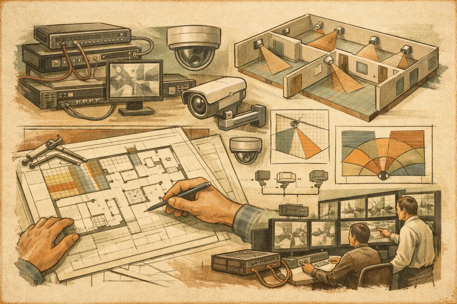
A DXF file can be an excellent starting point for a CCTV design, but it is not yet a usable security model. When teams import DXF security drawings, they often inherit hidden scale errors, duplicated linework, incomplete wall geometry, consultant layers that do not serve security planning, and reference data that may not transfer as expected. If those issues are not checked early, camera fields of view and pixel-density calculations can look credible while being based on the wrong physical dimensions.
The objective is not simply to display a CAD plan in a security design workspace. It is to convert the relevant parts of that drawing into traceable design inputs: verified scale, usable geometry, access points, critical areas, mounting locations, and routes that support both camera coverage and network topology.
Import DXF Security Drawings as Engineering Inputs
A DXF is a drawing exchange format, not a guarantee that every object is suitable for CCTV planning. The importing team should treat it as source material that requires technical review. This is particularly important when a drawing has passed through multiple disciplines, such as architecture, fit-out, electrical, fire protection, and security.
Start with the current issued drawing and record its revision, origin, and stated units. A plan labeled in millimeters may import at the expected size, while another file may have been drawn in meters, inches, or unitless coordinates. Do not assume that an on-screen dimension is correct merely because the plan appears proportionate.
Before placing cameras, identify one or more known physical dimensions that can be checked against the imported plan. A structural grid, a verified corridor length, or a clearly dimensioned room is usually more reliable than furniture or indicative layouts. This check becomes the basis for scale calibration.
The design output at this stage is a calibrated reference plan, not a finished security layout. That distinction matters when the drawing is later reviewed by an architect, installer, client, or authority reviewer.
Calibrate Scale Before Reviewing Coverage
Scale calibration has direct consequences for focal length selection, field of view, DORI planning, and pixel density expressed in pixels per meter or PPM. If a 20-meter lobby is accidentally represented as 20 feet, a camera cone may still look plausible on screen, but the calculated scene width and identification capability will be materially wrong.
Use a dimension with a known real-world value and set the drawing scale accordingly. Then validate the result against a second dimension in another area of the plan. A single reference can be misleading when a drawing has been stretched, exported incorrectly, or assembled from separate sources.
For large or complex sites, verify scale on each imported floor or zone. Mixed-use developments may contain separate tenant drawings, shell-and-core plans, parking layouts, and external works plans created by different consultants. Each file may have its own origin, layer standards, or units.
Scale calibration supports calculated design results. It does not verify as-built conditions. Ceiling changes, temporary partitions, racking, signage, fixtures, and revised door swings can all affect actual camera performance and must be reviewed during coordination and site verification.
Review Layers and Remove What Does Not Affect Design
DXF drawings frequently contain far more information than is needed for a CCTV design. Dense hatch patterns, furniture blocks, title blocks, dimensions, electrical symbols, and annotation layers can obscure the geometry needed to assess occlusion and camera placement.
Keep the layers that help define the environment: walls, columns, doors, glazed partitions, stairs, elevators, site boundaries, roads, gates, and significant equipment or fixed obstructions. Depending on the project, ceiling grids and reflected ceiling plans may also be useful for confirming mounting height, cable routes, and obstructions.
Hide or simplify layers that add visual noise without contributing to security decisions. This is not an instruction to delete the original drawing. Preserve the source file and create a design-ready view that is easier to audit. The goal is a plan where a reviewer can quickly see why a camera is located in a particular position and what may obstruct it.
Special attention is needed for blocks and external references. Some DXF exports flatten these objects into linework; others retain them in a way that does not import cleanly. If critical walls, doors, or building elements are missing, reconstruct only the geometry required for the coverage model and mark it for coordination. Do not infer concealed construction from incomplete CAD data.
Confirm What Counts as an Occlusion
Not every line in a DXF should block a camera field of view. A wall should generally be modeled as an occluding physical element. A door may block or permit a sightline depending on whether the design assumes it is open, closed, glazed, or access-controlled. Low furniture may affect a scene at certain mounting heights without creating a full obstruction.
This is where professional judgment is more useful than automated interpretation. A design tool can assist with wall recognition and geometry creation, but the imported linework still needs review against the building intent and, where available, site information. Blind spots should be identified from verified geometry rather than from every visible CAD line.
Build Security Geometry That Matches the Project Scope
Once scale and layers are controlled, create or review the physical geometry used for camera calculations. Walls, partitions, doors, columns, and major fixed assets should represent the expected operational environment at the level of detail needed for the security objective.
A reception desk may be relevant if it masks a visitor's lower body or creates a close-range blind spot. A small chair symbol probably is not. Warehouse pallet racking, on the other hand, can be a primary occlusion and should be modeled or considered as a defined operational constraint. For external areas, vehicle barriers, perimeter walls, gates, landscaping, and building projections may alter practical sightlines.
The required level of detail depends on the purpose of the design. A concept-stage scheme may use indicative geometry and state its assumptions. An installation-ready design requires closer coordination with architectural, structural, MEP, and operational information. Treat these as different deliverables, even when they begin from the same DXF source.
Place Cameras Against Defined Coverage Objectives
After importing and calibrating the drawing, camera placement should begin with the required observation task, not with an arbitrary camera spacing rule. Define whether each area requires detection, observation, recognition, or identification under the project's chosen DORI approach. Then select candidate camera specifications based on sensor size, resolution, focal length, mounting height, direction, and tilt.
A wide field of view can provide useful situational awareness in an open lobby but may not deliver the pixel density needed to identify a person at the far end. A tighter focal length can improve distant detail while increasing the need for additional cameras, careful overlap, and consideration of movement paths.
Use the imported geometry to test each field of view for wall collisions and occlusions. Review coverage at the intended target plane rather than relying only on a cone drawn across the plan. A camera mounted at a higher elevation may see beyond some obstacles, while its tilt can reduce usable detail at distance. Conversely, a low-mounted camera may be more vulnerable to obstructions, tampering, and glare.
CCTV Design Tool Online supports this workflow by keeping calibrated plans, walls, camera parameters, coverage calculations, and documentation in one persistent design workspace. The value is traceability: a change to a camera position or plan geometry can be reviewed alongside its effect on field of view, DORI, PPM, blind spots, and coverage overlap.
Coordinate Network Planning Before the Drawing Becomes a Report
A DXF-based CCTV layout should also support early coordination of network and infrastructure requirements. Camera symbols alone do not communicate switch locations, containment constraints, uplink paths, power strategy, or the difference between a local edge switch and a central equipment-room connection.
As cameras are added, organize them by zone, floor, network segment, or logical system grouping. This makes it easier to review camera counts, likely cable pathways, PoE demand assumptions, and network topology with ICT and electrical stakeholders. Final cable lengths, bandwidth, storage, switch capacity, and power calculations require project-specific inputs and verified equipment data, but the layout should expose these dependencies rather than postpone them.
Produce a Reviewable Deliverable
The final drawing should explain the design logic, not just show camera icons. Include a readable plan, camera IDs, viewing direction, relevant coverage areas, and a camera schedule that records the technical assumptions behind each position. Where appropriate, document focal length, resolution, mounting height, tilt, target objective, and calculated pixel-density or DORI outcome.
State important assumptions clearly. Examples include assumed door positions, unavailable ceiling data, pending furniture layouts, indicative external lighting, or areas awaiting site verification. This gives reviewers a structured basis for comments and prevents calculated results from being presented as confirmed installation performance.
A disciplined DXF import process turns a CAD background into a reliable starting point for security engineering. The most useful question is not whether the drawing loaded successfully, but whether every coverage decision can be traced back to calibrated scale, reviewed geometry, and a defined security objective.