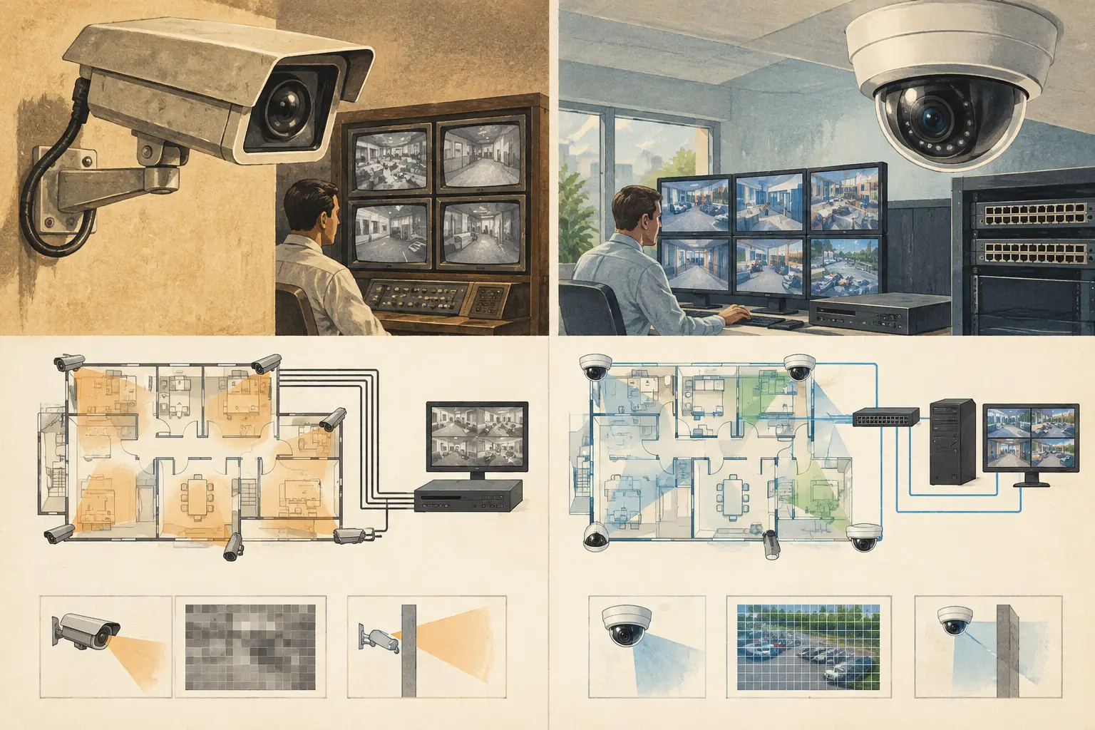
A camera schedule can look straightforward until the existing building infrastructure enters the conversation. A warehouse may already have usable coaxial cable, while a new campus may require fiber uplinks, PoE switching, and centralized video management. The decision between IP versus analog surveillance systems is therefore not simply a choice between old and new technology. It changes how coverage is calculated, how the system is powered and connected, what evidence detail is achievable, and how the design is documented for installation and review.
For most new, complex, or expanding projects, IP is the default technical direction. Analog still has a valid role where coax infrastructure is sound, the scope is limited, and the required operational outcome can be met without replacing the transmission network. The correct choice depends on the site, the required identification task, the lifecycle plan, and the cost of achieving a verifiable design outcome.
IP versus analog surveillance systems: the engineering difference
An analog camera converts the scene into a video signal that travels over coaxial cable to a recorder, typically a DVR or an XVR that can support multiple signal types. Modern high-definition analog formats can deliver substantially better images than legacy composite systems and may be practical for retrofit work.
An IP camera encodes video at the camera and sends digital data across an Ethernet network. It is commonly powered through Power over Ethernet, although local power or other arrangements may be used where required. The camera becomes a network endpoint, with an IP address, bandwidth demand, switch-port requirement, and often a larger range of configuration options.
This transport difference affects the whole design workflow. Analog planning centers on camera position, lens selection, coax route length, power distribution, recorder channels, and signal compatibility. IP planning includes the same physical questions, but adds network topology, PoE power budget, uplink capacity, VLAN or segmentation requirements defined by the project team, storage throughput, and device management.
Neither architecture corrects poor camera placement. A high-resolution IP camera pointed across an open lobby at an excessive distance may not provide the pixel density needed for identification. Similarly, a well-placed analog camera can provide useful monitoring at a doorway when the field of view, focal length, mounting height, and lighting conditions are appropriate.
Start with the operational requirement, not the cable type
The most reliable specification starts with what the operator must do with the image. Is the goal to monitor activity across a loading yard, recognize a known person at a staff entrance, identify an unknown person at a controlled doorway, or read information in a defined lane? Those are different design tasks.
DORI and pixel density provide a structured way to translate those tasks into camera requirements. Detection, observation, recognition, and identification each demand a different level of scene detail. The relevant calculation depends on the camera resolution and the width of the observed scene at the target distance. It is not enough to specify a camera by megapixel count alone.
For example, increasing resolution can improve available pixels across a scene, but only if the lens, sensor size, compression settings, lighting, motion, and scene geometry support the intended result. A wide-angle camera covering an entire parking lot may be suitable for detection and situational awareness while remaining unsuitable for identification at its far boundary. A narrower field of view may produce more pixels on a gate or doorway, but it covers less area and may introduce blind spots beside the target zone.
This is where the IP advantage often becomes practical rather than theoretical. Higher-resolution camera options, vari-focal lenses, multi-sensor devices, and analytics-capable models can give designers more ways to solve a detailed coverage problem. However, an IP specification should still be justified through field-of-view and PPM calculations, not assumed from a product label.
Coverage quality is independent of transmission method
A coverage drawing should show what each camera can see after physical geometry is considered. Walls, partitions, shelving, columns, doors, gates, and changes in elevation can all create occlusion. A camera cone drawn over a floor plan without accounting for these elements is only an initial visual indication, not a dependable coverage assessment.
Mounting height and tilt are equally significant. Raising a camera can increase visible floor area but may reduce facial detail, increase the angle of view, and make objects behind tall obstructions harder to observe. Lower mounting can improve detail at a target plane but may increase vulnerability and leave more near-field blind spots. The camera direction, focal length, sensor size, and mounting position must work together.
This applies to both system types, although IP projects more commonly involve diverse camera models and resolutions. A mixed IP design can be efficient when each camera is selected for a defined task: overview coverage, doorway recognition, corridor observation, perimeter monitoring, or targeted identification. It can also become difficult to review if the schedule does not clearly record the model-independent technical inputs and expected coverage outcome.
A calibrated floor plan helps maintain traceability. Once scale calibration is correct, a designer can position cameras, test fields of view, review DORI zones, and identify overlap or blind spots against the actual geometry. The calculation is a design result, not a guarantee of field performance. Installation tolerances, final ceiling layouts, lighting, scene movement, and the selected manufacturer's configured performance must still be checked during commissioning.
Cabling, power, and network topology
The strongest case for analog is often existing coaxial infrastructure. If cable routes are accessible, tested, and fit for purpose, upgrading cameras and recorders may avoid disruptive rewiring. This can be particularly relevant in occupied buildings, small retail sites, and phased refurbishments. The installer should still verify cable condition, route lengths, power arrangements, connectors, and compatibility with the selected camera and recorder format.
IP systems typically simplify the edge connection by carrying power and data over a single Ethernet cable through PoE. That does not make the infrastructure simpler overall. Switches need sufficient PoE budget, ports need to be allocated, cabinets require thermal and power planning, and uplinks must carry the aggregate traffic from connected cameras. Larger sites may require distribution switches, fiber backbone links, and resilient paths determined by the project network design.
Bandwidth is driven by more than resolution. Frame rate, codec, scene complexity, image noise, bitrate controls, recording mode, and event activity all affect actual traffic. A design should estimate normal and peak loads, then validate them against switch capacity, uplink capacity, recorder or server throughput, and retention requirements. Using a nominal bitrate without documenting the assumptions can lead to under-sized links and unpredictable recording behavior.
Analog systems avoid IP switching at each camera, but they still require organized power distribution, recorder capacity, and cable management. Long coax runs can also introduce practical constraints that must be assessed during the site survey. The simplest cabling choice is not always the lowest-risk lifecycle choice.
Storage and system growth change the comparison
Both analog and IP systems require storage planning based on camera count, recording settings, retention period, and operational requirements. IP systems may create larger storage demands because they are frequently specified at higher resolutions or frame rates. That can be justified where the scene requires more pixel density, but it should not be treated as a default benefit.
Scalability is usually where IP has a clearer advantage. A well-planned network topology can support additions across multiple buildings, centralized monitoring, and more flexible recorder or server architectures. Yet expansion consumes switch ports, PoE capacity, uplink bandwidth, IP addressing, rack space, and storage. A network diagram should therefore be treated as part of the CCTV design deliverable, not as a separate afterthought for the ICT team.
Analog can remain easier to extend at a small scale when unused coax routes and recorder channels already exist. Once the site grows across buildings or requires many new routes, the operational convenience of IP may outweigh the apparent saving from retaining legacy infrastructure.
A disciplined selection workflow
The decision is easier when it follows a documented sequence. First, define each surveillance objective and the required DORI outcome at relevant target locations. Next, import and calibrate the drawing, model walls and major obstructions, and test camera positions, focal lengths, heights, tilt, coverage overlap, and blind spots.
Then compare viable camera specifications using technical parameters rather than brand assumptions. For an analog option, document coax routes, power, recorder channels, and upgrade constraints. For an IP option, document camera bandwidth assumptions, PoE demand, switch locations, uplinks, and the proposed network topology. Finally, produce a camera schedule and technical report that clearly separates calculated coverage from conditions requiring site verification.
CCTV Design Tool Online supports this type of design review by keeping floor-plan geometry, camera specifications, field-of-view analysis, DORI coverage, and network planning in one persistent workspace. It can help teams communicate the basis of a design, but qualified professionals still need to review project-specific installation, manufacturer, authority, and operational requirements.
The useful question is not whether IP has replaced analog everywhere. It is whether the selected system gives the project team a traceable path from operational requirement to camera position, pixel density, infrastructure capacity, and a deliverable that installers and reviewers can act on.