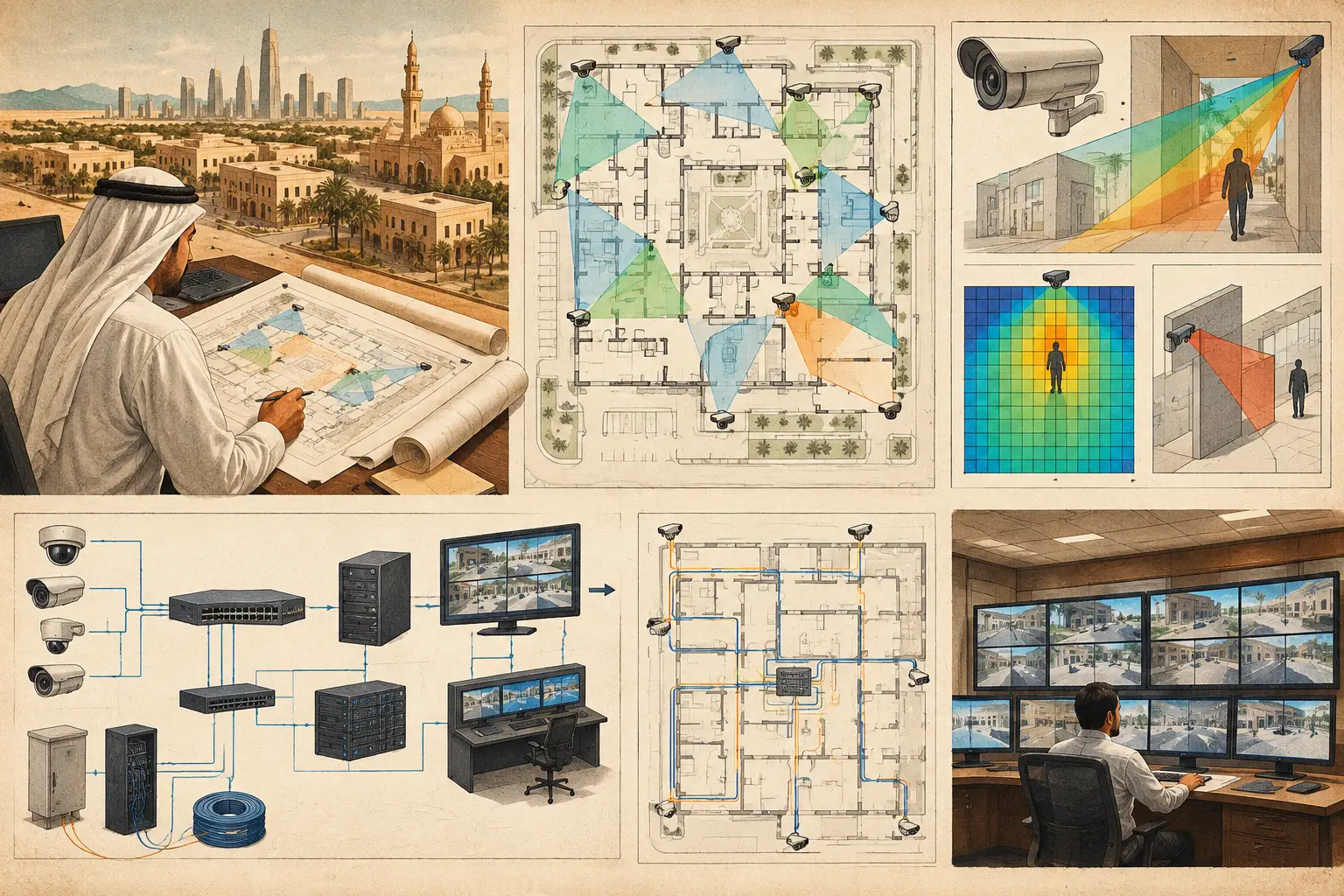
A mixed-use development is handed to the security team with architectural plans, a preliminary camera count, and a request for coverage at entrances, parking areas, retail corridors, and service yards. The camera count may look reasonable on a drawing, but it does not answer the engineering questions that determine whether the system can support its intended use. This Middle East CCTV project example shows how a design team can turn a concept layout into a reviewable technical design without treating a camera cone as proof of usable coverage.
The example is hypothetical. It is intended to demonstrate a disciplined workflow, not to represent an approved design, a jurisdiction-specific requirement, or actual field performance. Final requirements should be confirmed by the project security consultant, relevant stakeholders, and any applicable authority.
Project scenario and design inputs
Consider a six-story mixed-use building with ground-floor retail, office floors above, a basement parking level, loading access, roof plant areas, and external pedestrian approaches. The development team wants a system that supports general situational awareness across public circulation routes, observation of vehicle entries and exits, and identifiable coverage at selected access-control points.
The available inputs include architectural floor plans, reflected ceiling information for the entrance lobby, parking layouts, façade elevations, and an initial list of security objectives. The plans are not all issued at the same scale. The parking plan has been revised after the original camera schedule was prepared, and the loading-yard drawing does not show every proposed sign, canopy, or service enclosure.
This is common project reality. A CCTV design is only as dependable as the geometry, camera assumptions, and design criteria used to create it. The first task is not selecting a manufacturer or adding cameras. It is establishing a controlled design basis.
Middle East CCTV project example: establish the design basis
The team imports each relevant plan into a persistent design workspace and performs scale calibration using known drawing dimensions. This step is not administrative. A scale error changes estimated target distance, field of view, pixel density, and cable-run assumptions. A camera that appears to cover a doorway on an uncalibrated drawing may be positioned too far away to deliver the required detail.
Walls, doors, glazed partitions, columns, vehicle barriers, and major equipment zones are then reviewed as physical geometry. A camera field of view should be evaluated against occlusion, not simply displayed as an unobstructed triangle. For example, a lobby camera mounted near a ceiling bulkhead may have a clear view of the main doors while losing the face of a person standing close to the reception counter. In the basement, a column line can create repeated blind spots between parked vehicles.
The team records the intended observation task for each area before refining the camera selection. General monitoring of a corridor has a different pixel-density requirement from recognition at a controlled entrance or identification at a transaction point. DORI provides a useful framework for documenting those distinctions: detection, observation, recognition, and identification. It is a design reference, not a guarantee of image quality under every lighting, motion, compression, scene-contrast, or installation condition.
Define camera parameters before judging coverage
For each proposed camera, the team enters the known or assumed technical parameters: resolution, sensor size, focal length or varifocal range, mounting height, direction, tilt, and target area. These values affect both field of view and pixels per meter, or PPM, at different distances from the camera.
A wide-angle camera can show a broad lobby floor area, but its PPM decreases with distance. That may be appropriate for observing circulation and queues, yet insufficient for a requirement focused on recognizing a person entering through a specific lane. A longer focal length may improve pixel density at the entrance, but it can reduce contextual coverage and may require a second camera to maintain awareness of the surrounding area.
This trade-off is where generic camera counts fail. The appropriate design may be one camera, two cameras with overlapping roles, or a revised mounting position. It depends on the required task, scene geometry, lighting concept, privacy constraints, and available mounting infrastructure.
Working through three critical areas
Main entrance: separate overview from facial detail
The preliminary layout includes a single panoramic camera above the lobby doors. Its field of view captures the doors, visitor seating, and a portion of reception. The coverage visualization looks efficient, but the calculated pixel density at the outer edges of the entrance is lower than the design objective for recognition.
The design team retains the overview camera for situational awareness and adds a dedicated camera aligned with the entry path. The second camera is placed to reduce extreme viewing angle and to provide better target presentation through the doorway zone. Its mounting height and tilt are reviewed to avoid seeing only the top of a subject's head.
The two views overlap at the threshold, but that overlap is purposeful. One camera provides context if an incident begins outside the doors; the other supports a more detailed view at the access point. The report should state the intended function of each camera rather than implying that every camera serves every evidential purpose.
Basement parking: map occlusion, not just open floor area
The original parking plan shows four fixed cameras covering vehicle aisles. When walls, columns, ramps, and parked-vehicle zones are modeled, the design review identifies blind spots around stair cores and at the turn into the loading access lane. Camera cones passing through a structural column are immediately visible as an unrealistic assumption.
The team adjusts two camera directions and introduces a targeted view toward the ramp transition. Rather than claiming complete coverage of every parked vehicle, the design documents the areas intended for aisle observation, vehicle movement monitoring, pedestrian route awareness, and controlled entry/exit coverage. This makes the limitations traceable for the project owner.
The review also considers lighting conditions. A calculated DORI result based on geometry and camera parameters does not verify nighttime performance. Low-light behavior, infrared reflections, headlight glare, scene illumination, and image settings require verification against the selected equipment data and, where appropriate, site testing.
Loading yard: coordinate security with operations and ICT
The loading yard requires coverage of the vehicle gate, dock doors, and pedestrian access route. A camera mounted high on the building façade gives a useful overview, but the gate itself is too far away for the required target detail. A separate gate-facing camera is proposed with a narrower field of view.
This decision creates a network-planning consequence. The new location needs a pathway, network switch capacity, power-over-Ethernet assessment, and allowance for outdoor enclosure requirements. The CCTV designer should not leave these implications until installation. A camera layout and network topology need to develop together, particularly where distances, building risers, external trenches, fiber links, or local communications cabinets affect the scope.
Produce a reviewable deliverable
At the end of the design stage, the output is more than a marked-up floor plan. A structured deliverable can include calibrated drawings, camera locations, fields of view, mounting assumptions, camera parameter schedules, DORI or PPM analysis, blind-spot observations, overlap rationale, and preliminary network connectivity notes.
This material supports different reviewers in different ways. The security consultant can assess whether operational objectives were interpreted correctly. The architect can identify coordination issues with ceilings, façades, and finishes. The ICT team can review likely network pathways and cabinet locations. The installer receives clearer intent than a simple symbol plan, reducing the risk of unapproved field changes.
CCTV Design Tool Online can support this workflow by keeping floor-plan calibration, physical geometry, camera specifications, field-of-view visualization, DORI analysis, and reporting within one browser-based workspace. The calculations remain dependent on the accuracy of the inputs, and qualified professionals should verify the design against project requirements and actual site conditions.
What this example changes in practice
The useful outcome is not a larger camera schedule. It is a design that explains why each camera exists, what task it supports, where its limitations begin, and what coordination is needed to install it as intended. That clarity is especially valuable when drawings change, because the team can revise a measured model rather than restart a collection of disconnected files.
A credible CCTV design does not promise that every incident will be captured perfectly. It creates traceable decisions before procurement and installation, when camera position, focal length, mounting height, coverage overlap, and network pathways can still be improved at relatively low cost.