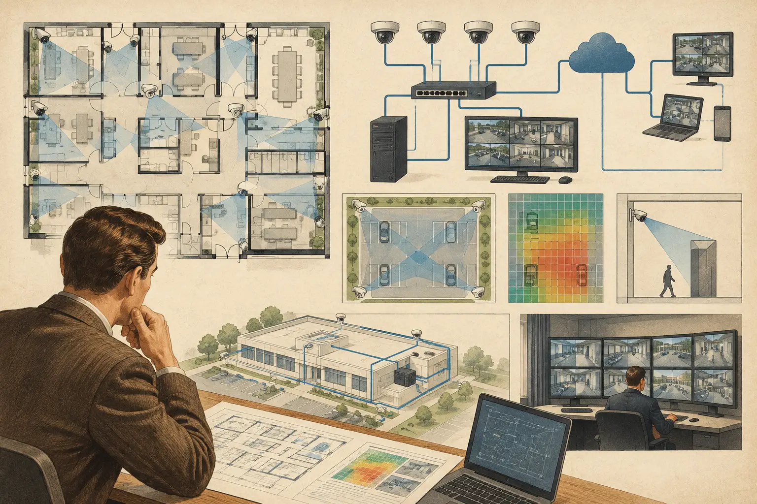
A camera layout can satisfy DORI, pixel density, field of view, and blind-spot requirements while the supporting network is still undersized or difficult to maintain. A network topology design review brings the physical-security and ICT views together before equipment is ordered or installed. The objective is not simply to draw switches and cables. It is to confirm that every camera has a practical path for power, data, recording, monitoring, and fault diagnosis.
For CCTV projects, topology should be reviewed alongside the calibrated floor plan, camera schedule, coverage analysis, and equipment-room locations. Separating these decisions often creates avoidable changes later: a camera is moved to improve identification coverage, then exceeds a PoE cable route, overloads a switch, or creates an unplanned uplink bottleneck.
Start With Verified Camera and Site Inputs
A useful review begins with traceable inputs rather than assumed device counts. Confirm the number of cameras in each area, their proposed resolution, frame rate, codec settings, recording mode, and expected scene activity. These variables affect network traffic substantially. A fixed indoor camera observing a quiet corridor will not generate the same traffic pattern as a multi-sensor camera watching a busy vehicle entrance.
Camera placement also affects the network design. Mounting height, tilt, focal length, sensor size, and direction determine the required camera position for the intended DORI objective. When a position changes to resolve an occlusion or achieve the needed pixels per meter, the nearest containment route, telecom room, and PoE source may change as well.
The site drawing must be scale-calibrated before cable distances are treated as design inputs. A topology diagram may show a logical connection from camera to switch, but the physical route must account for risers, ceilings, service corridors, external ductwork, fire-rated boundaries, and accessible containment. Measured route length, not straight-line plan distance, is what informs copper Ethernet feasibility and fiber decisions.
Review the CCTV Network Topology by Layer
A clear topology review separates the physical layout from the logical service path. Both need to agree.
Edge Layer: Camera Connections and PoE
At the edge, review which cameras connect to each access switch and whether each switch port can provide the required PoE class and total power budget. A switch with sufficient ports may still be unsuitable if its available PoE budget is lower than the combined peak load of cameras, illuminators, heaters, PTZ motors, or other powered devices.
Use manufacturer-verified power values where available, and consider operating states rather than idle consumption alone. A PTZ camera using heaters or infrared illumination can draw differently under adverse conditions. The design calculation is a planning input, not a substitute for confirming the final equipment datasheet and installation conditions.
Port allocation also deserves attention. Reserve capacity may be sensible in a growing site, but excessive spare capacity distributed across many small switches can add cost and support complexity. The right margin depends on the client’s expansion plan, criticality, cabinet space, and maintenance model.
Aggregation Layer: Uplinks and Traffic Concentration
The most common network risk is not a single camera connection. It is traffic concentration at the uplink. Estimate the cumulative camera bitrate for each access switch, then compare it with uplink capacity, expected headroom, and the traffic pattern to the video management system, recording servers, viewing clients, and any analytics infrastructure.
Do not assume that a camera’s quoted maximum bitrate will always be transmitted, or that average bitrate is always enough for design. Constant bitrate and variable bitrate settings behave differently. Scene complexity, motion, low-light behavior, compression configuration, frame rate, and retention settings all influence the result. Document the assumptions used so the design can be reviewed when camera settings are finalized.
Where multiple switches aggregate to one distribution point, review concurrent traffic rather than only each branch in isolation. High-resolution cameras, multi-sensor devices, and client viewing during an incident can change the loading profile. It may be appropriate to segregate traffic logically, increase uplink capacity, or revise the recording architecture. The correct approach depends on the wider enterprise network and the responsibility boundaries between the security integrator and ICT team.
Core, Recording, and Client Paths
A topology is incomplete if it ends at an uplink. Trace each camera stream to its intended recording destination and identify how operators, investigators, and authorized client devices access live and recorded video. Confirm the network locations of recording servers, storage, management servers, workstations, and remote monitoring connections where they are within project scope.
This does not require the CCTV designer to define every enterprise networking policy. It does require a documented handoff: which VLAN or network segment is proposed, where routing occurs, who provides addressing and switch configuration, and who validates connectivity before commissioning. Ambiguity at this point is a frequent cause of installation delays.
Test Resilience Against the Project Risk Profile
Resilience is not automatically better because it is more complex. A small office installation may accept a single access switch and a single uplink if downtime can be managed operationally. A transport facility, campus, or critical site may need carefully reviewed redundant paths, diverse routes, dual power arrangements, or distributed recording functions.
The review should identify single points of failure and record whether they are accepted, mitigated, or outside the security contractor’s scope. This is more useful than adding redundancy symbols to a diagram without confirming physical route diversity. Two fiber links placed in the same tray may provide device-level redundancy while remaining vulnerable to the same physical incident.
Consider these review questions before freezing the design:
- Is there a known connection path from every camera to recording and authorized viewing services?
- Does each PoE switch have enough ports, power budget, cabinet space, and thermal allowance for its assigned devices?
- Are estimated uplink loads based on documented camera settings and realistic simultaneous traffic?
- Do cable-route lengths and environmental conditions support the selected media type?
- Are critical single points of failure visible to the client, security team, and ICT reviewers?
- Are expansion capacity, labeling, and handover responsibilities defined?
Coordinate Physical Geometry With Network Locations
Topology diagrams are often created after camera positions have been approved, but that sequence can conceal a conflict. A field-of-view review may reveal that a camera needs to move away from a wall corner because a doorway, racking system, or façade projection creates an occlusion. The new location may improve pixel density at the target but require a longer cable route or a different switch zone.
This is why the review should be iterative. Update the camera location, recheck the field of view and DORI result, revise cable routing, then validate port allocation and bandwidth. The same applies when architectural drawings change. A new partition can alter both sight lines and the practical route between the camera and telecommunications cabinet.
CCTV Design Tool Online can support this coordination by keeping calibrated drawings, physical geometry, camera coverage, and network planning in one persistent workspace. The calculated result should still be checked against approved drawings, final equipment data, containment design, and site conditions by qualified project professionals.
Produce a Review Package People Can Build From
The output of a network topology design review should be more than a presentation diagram. It should allow another engineer, installer, or project manager to understand the basis of the design without reconstructing it from separate spreadsheets and markups.
A practical deliverable identifies camera IDs, switch assignments, proposed cable media, uplink relationships, equipment-room locations, estimated bandwidth assumptions, PoE assumptions, and open coordination items. Align these references with the camera schedule and floor plans. If Camera C-27 is moved, the coverage drawing, switch-port schedule, cable route, and topology diagram should all reflect the same revision.
Keep calculated values distinct from verified field outcomes. Bandwidth estimates depend on final configuration. Cable routes depend on installation methods. Coverage depends on final mounting height, lens selection, aim, lighting, and physical obstructions. A disciplined review makes these dependencies visible early, where they can be resolved with less rework.
The best topology review leaves the project team with clear questions, accountable owners, and a design that can be tested during commissioning rather than explained after a fault occurs.