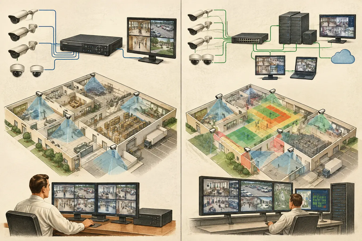
A recording platform decision can change a CCTV design long before the first camera is installed. NVR versus VMS architecture affects where video is recorded, how cameras are licensed and managed, how bandwidth moves across the network, and how readily the system can expand after handover. It should therefore be considered alongside field of view, pixel density, retention targets, and network topology, not treated as a procurement detail at the end of the project.
NVR versus VMS architecture: start with the operating model
An NVR, or network video recorder, is generally a purpose-built appliance that receives and records video from IP cameras. The recorder commonly provides local storage, camera management, user access, and a viewing interface in one device or appliance family. It is a relatively contained architecture, particularly when cameras, storage, and operators are located at one site.
A video management system, or VMS, is software that manages video across one or more recording servers, client workstations, storage tiers, and connected sites. The software layer can be deployed on commercial servers, virtual infrastructure, or a combination of local and centralized resources, depending on the product and project requirements. A VMS may also integrate video from multiple camera types and, where supported and specified, other security systems.
Neither model is automatically better. A small warehouse with 24 cameras and a single security office has different operational needs from a campus with multiple buildings, distributed control rooms, phased construction, and hundreds of cameras. The useful question is not which architecture is more advanced. It is whether the architecture supports the required scale, availability, operator workflow, and maintainability without creating unnecessary complexity.
Where an NVR architecture fits well
An NVR is often appropriate when the project has a defined camera count, limited sites, and a straightforward retention requirement. For a retail unit, small office, residential common area, or standalone plant room, an appliance-based system can reduce the number of infrastructure components that must be specified, configured, documented, and maintained.
The design still requires disciplined inputs. Camera stream settings determine recording load. Resolution, frame rate, codec, scene activity, and VBR or CBR settings all affect bandwidth and storage consumption. A 4K camera aimed at a busy entrance can create a substantially different storage profile from a lower-resolution camera viewing a quiet service corridor, even when both are assigned the same nominal retention period.
NVR systems can also be suitable for distributed locations where each site operates independently. Local recording avoids making continuous recording dependent on a wide-area connection. Remote viewing may still consume WAN capacity, especially if operators view high-resolution live streams rather than using substreams where the system supports them.
The trade-off is that scaling can become operationally fragmented. Adding cameras may require adding recorder channels, another appliance, or a replacement unit. Across several sites, operators may need to move between separate interfaces or use a central management layer, if available. The design team should document which cameras record to which appliance, the storage capacity allocated to each recorder, and the failure implications of losing a single unit.
Where VMS architecture earns its complexity
A VMS becomes more compelling when video operations extend beyond one appliance or one location. Typical drivers include a large camera estate, multi-building sites, centralized monitoring, varied retention requirements, phased expansion, or the need to manage recording resources across several servers.
Instead of treating recording as a fixed recorder channel count, a VMS design can allocate cameras to recording servers according to network zones, expected load, site resilience objectives, and operational ownership. For example, cameras in separate buildings may record locally to reduce backbone traffic, while authorized users view video through a centralized client environment. This is an architectural choice that must be matched to the VMS capabilities, server specifications, and network design actually selected.
VMS deployments also require more coordination. Server compute, storage performance, operating system lifecycle, virtual machine resources where used, licensing, client access, and software updates all become project considerations. Greater flexibility is valuable only when the organization has a clear operating model for it.
This does not mean a VMS is only for very large projects. A medium-sized facility may benefit from VMS architecture if it anticipates expansion, needs a consistent operator workflow across locations, or has existing server and ICT governance that supports the platform. Conversely, installing a server-based system simply because it appears more enterprise-oriented can add cost and support burden without improving the actual security outcome.
Architecture changes the CCTV design inputs
Camera placement remains the foundation of a usable CCTV system. A recorder or VMS cannot recover identification detail that was never captured because the focal length, sensor size, mounting height, tilt, or camera position was unsuitable. DORI planning and pixel-density targets should be established independently of the recording platform.
However, architecture changes how that camera design is delivered. Consider a long perimeter with cameras connected through field switches. If video is sent to a central recording room, uplinks must carry the aggregate camera bitrate with appropriate engineering margin. If recording is distributed across local buildings, backbone traffic may be lower during normal recording, but the design must still account for live viewing, playback, health monitoring, and any video export processes.
Storage design also becomes more granular with a VMS. Retention may differ by camera purpose, risk area, or operational policy. Cameras covering access points may have different recording schedules from low-risk general observation areas. These decisions should be documented as requirements, then calculated using verified stream assumptions. Manufacturer-reported bitrate tools and measured scene behavior can differ from early estimates, particularly in scenes with motion, low light, rain, foliage, or complex detail.
Availability should be stated precisely. Redundant recording, server failover, RAID storage, dual network paths, and camera edge storage can reduce particular failure risks, but each addresses a different scenario. They do not create uninterrupted recording under every possible fault. Define the events the design is intended to tolerate, the expected recovery behavior, and any accepted gaps in evidence capture.
A practical selection framework
Before selecting NVR or VMS architecture, establish four project facts:
- Camera estate and growth: Identify initial camera count, likely expansion, resolution classes, and whether future phases must operate within the same management environment.
- Site and network model: Map buildings, communication rooms, WAN links, local recording requirements, and the network topology between cameras, switches, servers, and operator clients.
- Operational workflow: Define who monitors video, where they work, how incidents are reviewed, and whether multiple sites need a unified search and viewing experience.
- Resilience and maintenance: Record acceptable failure scenarios, retention requirements, support responsibilities, replacement strategy, and the organization that will maintain servers, storage, and software.
These inputs prevent a common mistake: sizing storage first and deciding the operational model later. Storage is an output of camera streams, recording policy, retention, and resilience design. It is not a substitute for them.
Document the decision in the design package
The chosen platform architecture should appear clearly in the technical deliverable. A camera schedule alone is not enough. Reviewers need to see the relationship between camera IDs, locations, fields of view, recording destination, switch connections, network zones, and retention assumptions.
For each camera, document the intended purpose and calculated coverage result. This may include the field of view, focal length, sensor size, mounting height, tilt, distance to the target area, and the calculated pixel density or PPM at relevant points. Mark walls, glazing, shelving, gates, and other geometry that can create occlusion, blind spots, or misleading overlap on a plan.
Then connect that design to the recording architecture. An NVR design may show recorder allocation by building or cabinet. A VMS design may show recording server allocation, storage groups, client locations, and inter-site connectivity. The level of detail should suit the project stage, but assumptions should remain traceable so they can be reviewed when camera models, layouts, or network constraints change.
A browser-based workspace such as CCTV Design Tool Online can support this coordination by bringing calibrated plans, camera geometry, DORI and pixel-density calculations, coverage review, and structured reporting into the same design record. The recording platform still requires project-specific technical verification, but the camera and network inputs are easier to review when they are not scattered across separate drawings and spreadsheets.
Do not let the platform choice obscure the coverage objective
The most reliable decision is usually the one that makes the system easier to operate, support, and expand while preserving the detail needed at each monitored target. An NVR may be the disciplined answer for a contained site. A VMS may be justified where scale, distribution, and centralized operations create real value. Start with the required image detail and the physical environment, then select the recording architecture that can carry that design into daily operation.