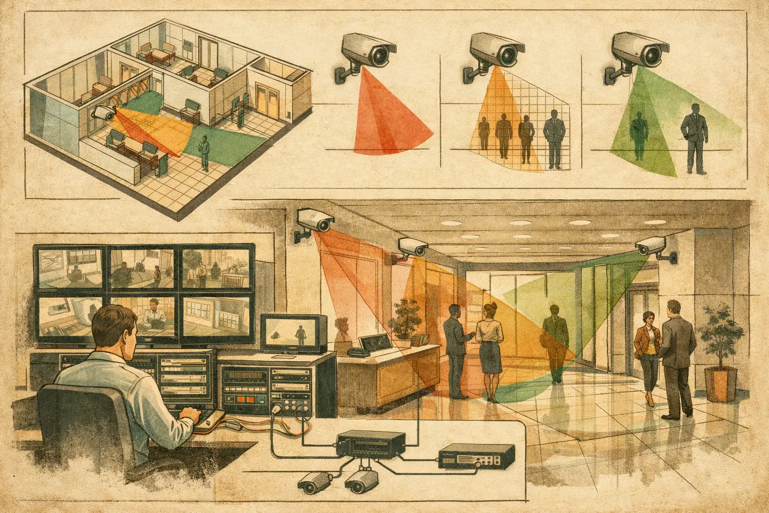
A lobby camera drawing can look convincing while still missing the only locations that matter: the face at the entry threshold, the visitor interacting with reception, or the route from elevators to a secure access door. This office lobby coverage example shows how to turn a simple floor plan into a reviewable CCTV design by testing geometry, pixel density, occlusions, and operational purpose rather than relying on camera cones alone.
The example uses illustrative camera parameters, not manufacturer-specific claims. Final camera selection and field performance should be verified against the chosen product datasheet, site lighting conditions, installation constraints, and the project security brief.
Start With the Lobby's Security Objectives
Assume a rectangular office lobby measuring 39 feet by 26 feet (12 m by 8 m). The main glazed entrance is centered on one short wall. A reception desk sits opposite the entrance, elevators are on the west side, and an access-controlled door to office space is behind the reception area. The ceiling height is 11.5 feet (3.5 m).
Before placing a camera, separate the required outcomes. The entrance needs an evidential view of people arriving and leaving. Reception needs a closer view of visitor and staff interactions. The general floor area needs situational awareness, including movement between the entrance, elevators, and office access door. These are related requirements, but they are not the same coverage task.
This distinction prevents a common design error: using one wide-angle overview camera to claim coverage of every activity in the lobby. A camera may see a person at a distance while providing insufficient pixel density for the project's required DORI outcome at that point. “In frame” is not equivalent to “fit for purpose.”
Office Lobby Coverage Example: Define the Inputs
Import the architectural drawing and calibrate its scale using a dimension that can be checked on site, such as the overall lobby width or a documented grid dimension. An incorrect scale calibration affects camera range, field of view, PPM calculations, and cable estimates, so this should be reviewed before camera placement begins.
For this example, use an 8 MP camera with a 3,840-pixel horizontal image dimension, an assumed active sensor width of 7.2 mm, and a 4 mm focal length. Those assumed optical inputs produce an approximate horizontal field of view of 84 degrees. At a 20-foot (6 m) target distance, the horizontal scene width is approximately 35.4 feet (10.8 m).
On a flat target plane at that distance, the simplified pixel density is:
`3,840 horizontal pixels / 35.4 feet = approximately 108 PPM`
That figure is a design calculation, not a promise of facial identification or recorded-image quality. Compression, motion blur, lighting, camera angle, focus, lens distortion, sensor performance, and VMS settings can materially change actual results. The relevant PPM target should come from the project brief and be evaluated at the specific target plane, not simply at the far end of a camera cone.
Position Cameras by Function, Not by Room Center
Camera 1: Entry and circulation overview
Mount the first camera near the reception-side ceiling line, approximately 10.2 feet (3.1 m) above finished floor level. Aim it toward the entrance and primary circulation route, with a moderate downward tilt. This position allows the camera to observe people crossing from the entrance toward elevators, reception, and office access.
The calculated 84-degree field of view is wide enough to include much of the 26-foot lobby width at a suitable distance. However, its useful pixel density will vary across the room. People near the entrance may be farther from the camera than those at reception, while edge locations may be affected by perspective and lens distortion. The design should therefore draw assessment lines or target zones at the entrance, elevator approach, and office access route rather than assigning one PPM value to the whole room.
A ceiling-centered overview may appear more symmetrical on a drawing, but it often creates poor face angles at the entry. In this example, offsetting the camera toward reception gives a better view of approaching visitors while preserving operational context.
Camera 2: Reception interaction zone
Add a second camera to cover the reception counter as a distinct target area. Position it so the camera sees the public side of the desk and the likely visitor standing location without looking directly into a monitor or creating an excessively steep overhead view. A mounting height near 9.8 feet (3 m) may be practical, subject to ceiling services and architectural coordination.
Use a narrower field of view for this camera. For example, retaining the assumed 7.2 mm sensor width and changing to a 6 mm focal length produces an approximate 62-degree horizontal field of view. At a 10-foot (3 m) target distance, that equates to a horizontal scene width of roughly 11.8 feet (3.6 m), or about 325 PPM using the 3,840-pixel image width.
The purpose is not to maximize PPM everywhere. It is to place higher useful detail where the security process requires it: visitor registration, credential presentation, and interactions at the desk. If the desk is long, curved, or split by a barrier, one camera may not provide consistent coverage across all positions. Two narrower views can be more defensible than one wide view, although they add cost, network load, and review complexity.
Camera 3: Conditional access-door coverage
A third camera may be needed if the secured office door is outside the usable field of either existing camera, is concealed by reception furniture, or requires a separate detail level. This is common when an architectural feature, decorative partition, or elevator lobby creates a visual break.
Do not add the camera merely because there is an unfilled corner on the plan. First define the intended outcome at that door: general movement monitoring, review of access events, or a higher-detail evidential view. Then calculate the field of view and PPM for the door plane and approach direction.
Test Occlusions Before Calling the Area Covered
In an office lobby, obstructions are frequently more consequential than room dimensions. Reception millwork can block lower-body movement. A column can conceal the elevator approach. Open glass doors can cause reflections or temporarily obstruct a camera's view. Seasonal displays, signage, queue barriers, and freestanding digital screens can all change the installed scene.
Review sight lines with walls and physical geometry represented in the drawing. A camera cone that passes through a wall, solid partition, or closed door is not coverage. Where possible, identify the opening direction of doors and show whether a camera view is intended through glazing, across an open doorway, or into a circulation zone.
Mounting height and tilt deserve the same scrutiny. Raising a camera may clear the reception desk, but it can worsen face angle at the entrance. Lowering it may improve target angle but introduce tampering risk or conflict with lighting fixtures. There is no universal mounting height for a lobby. The best option depends on the target plane, ceiling geometry, operational use, and architectural constraints.
Review Overlap and Blind Spots as Operational Risks
Coverage overlap is useful when it supports a real operational need. In this example, Camera 1 and Camera 2 should overlap around the reception approach. That overlap helps preserve context if a person moves from the entry route to the desk and allows reviewers to compare activity from two angles.
Too much overlap can be wasteful. If two wide-angle cameras produce nearly identical low-detail views, the system may consume additional switch ports, PoE capacity, storage, and recording bandwidth without improving the intended outcome. Conversely, a gap between the entrance and reception may leave a person only partially visible during the most important part of their movement.
Review the plan at several levels: the full lobby for overall field of view, target zones for pixel density, and obstruction layers for blind spots. It is also useful to check the image boundaries. Critical activity should not sit permanently at the extreme edge of a wide lens where distortion and framing changes can reduce practical value.
Coordinate Network and Installation Planning
Camera placement is also an ICT and construction coordination decision. Mark likely cable routes, communications closets, containment paths, and switch locations. Network topology should show whether each camera has a practical path to a PoE switch and whether the design requires intermediate cabinets or pathways that need coordination with other disciplines.
Estimate bandwidth and storage using the recording configuration and verified camera settings proposed for the project. Resolution alone is not enough to estimate network demand. Scene activity, frame rate, compression settings, VMS configuration, retention period, and analytic functions can change the result substantially.
The installation drawing should also identify mounting surface, camera direction, mounting height, focal-length assumption, target zones, and any field condition requiring confirmation. This makes the design traceable when a ceiling layout changes or a contractor asks why a camera cannot simply be moved several feet to avoid a service clash.
Turn the Example Into a Reviewable Deliverable
A professional lobby coverage package should let a client, installer, and reviewer understand what each camera is intended to achieve. Include the calibrated plan, camera schedule, field-of-view views, DORI or PPM assessments at relevant target planes, blind-spot observations, overlap areas, and preliminary network topology.
CCTV Design Tool Online can keep these elements in one persistent browser-based workspace, allowing the design team to model walls, place brand-agnostic camera specifications, assess coverage, and generate structured project documentation. The output still needs qualified engineering review and site validation, particularly where lighting, reflections, changing furniture, or architectural revisions affect the calculated geometry.
A good lobby design is not the one with the most camera icons on the plan. It is the one where every camera has a defined purpose, every critical target has been tested at the right distance and angle, and the documentation explains the reasoning well enough for the project team to build and review it with confidence.