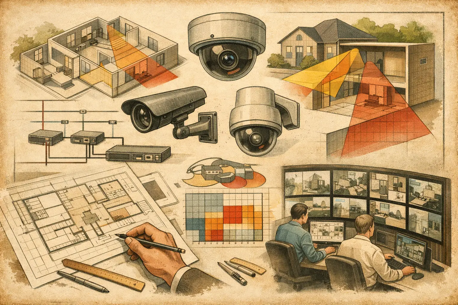
A security drawing review guide is most useful when it turns a marked-up floor plan into a set of verifiable engineering decisions. A camera symbol on a drawing does not establish usable identification coverage, account for a new partition wall, or show whether a network route is practical. The review must connect the drawing geometry to camera optics, operational objectives, physical constraints, and installation documentation.
For CCTV projects, the most expensive review issues are often introduced before procurement or installation: an uncalibrated plan, a field of view drawn without considering walls, a camera selected from resolution alone, or a schedule that does not match the plan. A disciplined review process finds these issues while changes are still manageable.
Start with the drawing basis and project brief
Before reviewing camera locations, establish whether the drawing is a reliable basis for design. Confirm the drawing revision, its source, the building level or site area represented, and whether it reflects the current architectural and MEP coordination status. A design can be internally consistent and still be unsuitable if it is based on a superseded layout.
Scale calibration is the first technical check. Use a known dimension, such as a gridline distance, room dimension, or surveyed site reference, to calibrate the plan. Then validate the result against at least one separate known dimension. A small scale error can materially change calculated field of view widths, mounting distances, and pixel density at the target.
The project brief should also identify what each camera must achieve. General observation of a lobby is not the same as recognition at an entry point or identification at a controlled doorway. Define the operational target, the relevant area, and the required level of detail before judging whether a proposed camera is appropriate. DORI provides a useful framework for communicating detection, observation, recognition, and identification objectives, but the required outcome must remain project-specific.
Review physical geometry before coverage
A coverage cone drawn over a floor plan is only meaningful if the physical model is credible. Review walls, glazing, doors, gates, counters, shelving, columns, ceilings, and external structures that may affect the camera's view. Pay particular attention to features that are absent from an early architectural plan but likely to appear during fit-out.
Check camera mounting assumptions
For each device, verify the mounting location, mounting height, direction, tilt, and approximate installation surface. A ceiling-mounted camera may appear well positioned on a plan but be impractical because of a bulkhead, sprinkler zone, access panel, or lack of a suitable fixing point. At external locations, confirm whether poles, façades, canopies, landscaping, vehicle paths, or future signage may create occlusion.
Camera orientation should be reviewed against the likely direction of travel. A wide angle view of a doorway can support observation, but a face captured at a steep horizontal or vertical angle may not satisfy an identification objective. This is one reason camera placement cannot be reviewed as a symbol-only exercise.
Treat openings and transparent surfaces carefully
Doors and glazing are frequent sources of false confidence. An open doorway may provide sightlines on a drawing, while a normally closed opaque door does not. Glass may allow a visual line of sight but introduce reflections, glare, tint, or poor low-light performance that cannot be determined from geometry alone. The drawing review should record such assumptions for site verification rather than presenting them as confirmed performance.
Evaluate field of view, pixel density, and DORI
Once the model and camera positions are credible, review the calculated coverage. The relevant inputs include camera resolution, sensor size, focal length, mounting height, direction, tilt, and target distance. These factors determine the field of view and the pixel density available across the scene.
A wide field of view can reduce the number of cameras, but it spreads available pixels over a larger area. A narrow focal length may provide stronger pixel density at a critical target, yet it can introduce blind spots around the wider approach route. Neither choice is universally better. The correct decision depends on the stated DORI requirement, the target size, the environment, and the acceptable operational risk.
Review pixel density in pixels per meter, or PPM, at the actual point where the objective applies. For example, do not assess an entrance camera solely at the door center if people may approach through multiple lanes or at different stand-off distances. Likewise, a camera that meets a calculated PPM threshold on a flat plan may require further assessment where stairs, ramps, or changing elevations affect the target plane.
Calculated DORI and PPM results are design indicators, not proof of live performance. Lighting, motion blur, compression settings, scene contrast, lens quality, focus, and recorder configuration can all affect installed results. The drawing should therefore distinguish between calculated coverage and items requiring commissioning verification.
Identify gaps, overlap, and unnecessary duplication
Review every critical route and operational area as a sequence, not as isolated camera views. Follow a person or vehicle from the site boundary, parking area, or reception point through access-controlled doors, corridors, elevators, and sensitive zones. This makes blind spots easier to find, especially at turns, behind door swings, and between adjacent camera fields.
Coverage overlap is valuable where continuity or handover between cameras matters. It can help operators follow movement and provide a second view if one camera is obstructed. However, overlap consumes budget, network capacity, storage, and review effort. It should be intentional rather than a byproduct of placing cameras at regular intervals.
When duplicate views are found, compare their purpose before removing one. Two cameras that appear similar on plan may differ in focal length, target PPM, face angle, lighting condition, or resilience to a single obstruction. Conversely, two devices may both be providing broad observation while neither delivers the required detail at the controlled point. The review should identify the functional gap, not merely count cameras.
Coordinate the camera schedule and network topology
A drawing is incomplete when the camera plan, schedule, and network concept contradict one another. Each camera identifier on the drawing should match the schedule exactly. Confirm the specified camera type, resolution, lens or focal-length range, mounting height, direction, tilt, and intended purpose. If a design uses an adjustable varifocal lens, document the assumed focal length used for the coverage calculation. Installing it at a different setting changes the result.
Network review should trace devices to local cabinets, PoE switches, aggregation points, recording infrastructure, or wireless links where applicable. Confirm that the proposed routes are physically plausible and that the topology reflects the building's coordination constraints. Cable pathway availability, cabinet locations, power arrangements, and fire-stopping requirements require coordination with the relevant disciplines and qualified project professionals.
Bandwidth and storage calculations should use the intended stream settings and retention assumptions, not only the camera count. These values remain dependent on configuration, scene activity, codec behavior, and manufacturer-specific capabilities. Record the assumptions so they can be tested during detailed design and commissioning.
Produce a review record that can survive revisions
The strongest drawing review creates traceability rather than a vague approval comment. Mark each issue with a location, description, design impact, responsible party, and required action. Categorize whether the issue is a drawing discrepancy, geometry assumption, coverage concern, network coordination point, or site verification item.
A practical deliverable includes the calibrated drawing, camera layout, field-of-view visualization, camera schedule, DORI or PPM assessment, network topology, and an assumptions register. It should show revision status clearly. If an architectural change moves a wall or alters a doorway, reviewers should be able to see which cameras and calculations need re-evaluation.
CCTV Design Tool Online supports this workflow by keeping calibrated drawings, physical geometry, camera parameters, visual coverage, optical calculations, and technical reporting in one design workspace. The outputs still require engineering judgment and project-specific verification, particularly where site conditions differ from the drawing.
Use the review meeting to resolve decisions
A drawing review meeting should focus on decisions that affect scope, risk, or coordination. Ask whether each critical area has a defined surveillance objective, whether the calculated camera view supports it, and whether the camera can be installed and connected as shown. Where information is incomplete, assign a specific site survey or design action instead of accepting an unqualified assumption.
The most useful security drawings do not imply certainty where none exists. They show what has been calculated, what has been coordinated, and what must still be confirmed in the field. That clarity gives installers, consultants, owners, and reviewers a more reliable basis for the next project decision.