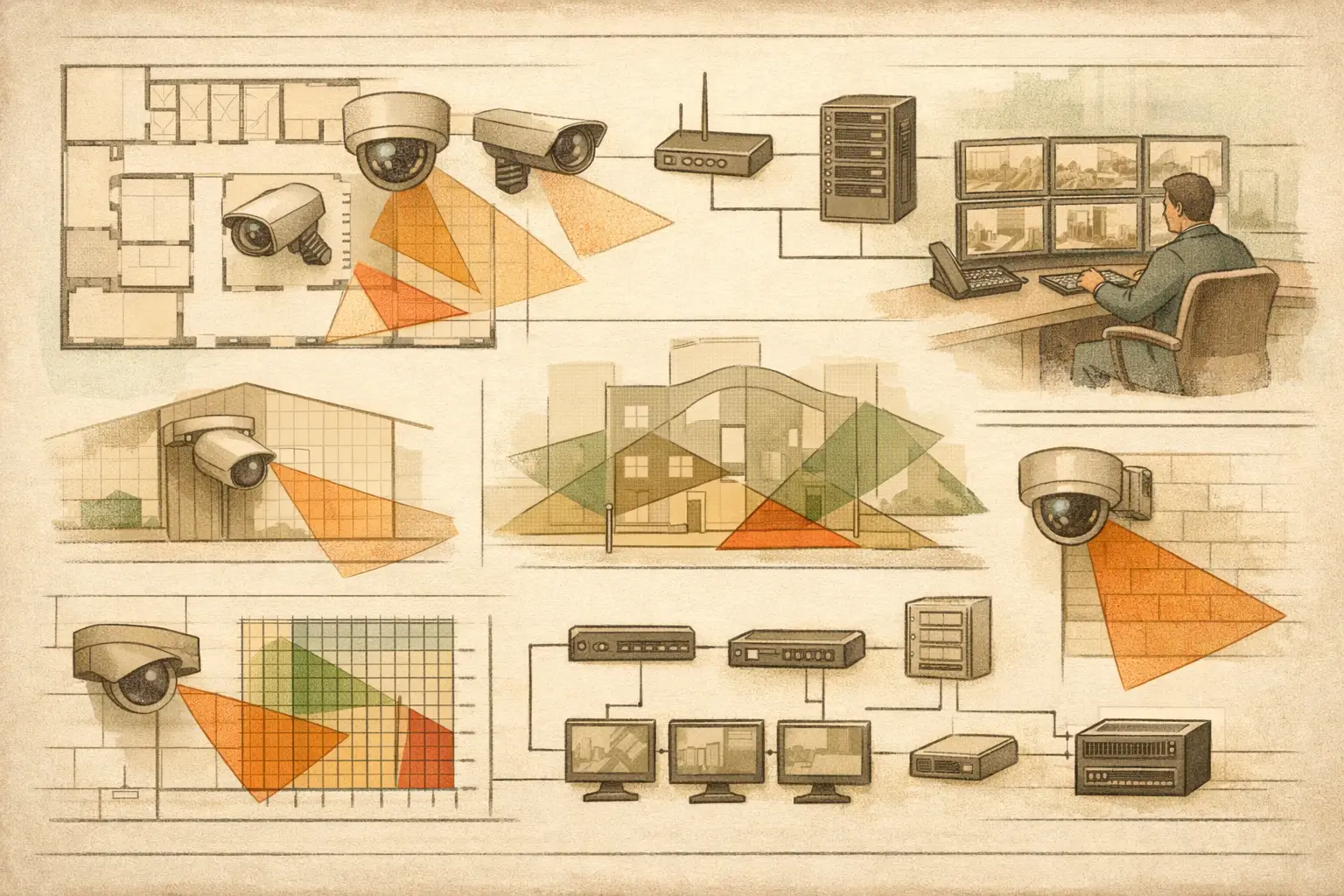
A surveillance retrofit guide should begin with the conditions already installed, not with a catalog of new cameras. Existing sites carry constraints that new-build projects do not: legacy cable routes, ceiling heights, occupied areas, fixed architectural features, restricted access windows, aging recorders, and camera positions chosen for requirements that may no longer apply. The objective is to establish what the system can demonstrably cover, what it cannot, and what must change to meet the current operational brief.
A retrofit is not automatically a full replacement. In some projects, a revised focal length, adjusted mounting height, or corrected camera direction resolves a material coverage issue. In others, the network, storage, camera hardware, and physical infrastructure are so interdependent that retaining legacy components creates more risk than replacing them. A disciplined survey and documented design model make that distinction visible before installation work begins.
Start With the Operational Requirement
Define the outcome required at each monitored area before reviewing the installed equipment. “Cover the lobby” is not a measurable requirement. A more useful requirement identifies the activity, target zone, identification need, operating conditions, and reviewing party. For example, a main entrance may require recognition at the approach and identification at an access-control point, while a loading yard may need detection across a broader perimeter zone.
DORI provides a useful language for this discussion: detection, observation, recognition, and identification. Each level requires a different pixel density, often expressed in pixels per meter or PPM. A camera that detects movement at the far end of a parking area may not provide enough pixel density to identify a person there. Treating these as separate outcomes prevents a common retrofit error: accepting a wide field of view as evidence of usable detail.
Requirements should also distinguish between continuous coverage and event-focused coverage. A corridor, cashier point, vehicle gate, or emergency exit may warrant a specific target plane and higher pixel density. General situational awareness areas may accept lower density if their role is to support response rather than establish identity. Confirm project-specific requirements with the client, security team, and qualified reviewers where regulatory or authority conditions apply.
Audit the Existing System Before Designing Changes
The site survey should capture both physical facts and technical facts. Record each camera's location, mounting height, direction, tilt, approximate focal length or lens setting, image quality, field of view, and visible obstructions. Also document the recorder or VMS environment, available switch capacity, power method, cable condition where known, and the current network topology.
Do not rely on a camera schedule alone. Schedules are frequently outdated after tenant changes, repairs, phased extensions, or substitutions during installation. A camera labeled as a 4 MP varifocal unit may be operating at a different resolution, frame rate, lens position, or stream configuration than the schedule suggests. Manufacturer-specific performance should be verified from the relevant datasheet and, where possible, the active device configuration.
Physical geometry deserves equal attention. Walls, glazing, columns, racking, doors, soffits, signage, and landscaping can create occlusion that a simple camera cone does not reveal. An open doorway can become a closed door. A warehouse aisle can change after racking is installed. Outdoor vegetation and parked vehicles may affect practical sightlines even if the original drawing appeared clear.
Import the latest floor plan or site drawing and calibrate its scale against a verified dimension. Then review walls, openings, and other physical geometry before placing or assessing cameras. Scale calibration errors propagate through every subsequent calculation, including field of view, target distance, PPM, cable estimates, and coverage drawings.
Model Coverage, Not Just Camera Icons
A credible retrofit design shows each camera's field of view in relation to the actual space. Configure the camera using known or proposed inputs: resolution, sensor size, focal length, mounting height, tilt, and direction. If a specification is uncertain, identify the assumption rather than presenting it as confirmed.
Review coverage at the required target areas, not only at the center of the image. Wide-angle cameras often appear satisfactory when viewed as a cone on a plan, yet their pixel density falls sharply as the scene width increases. Conversely, a narrow field of view may achieve the required identification detail but leave approach routes and adjacent doors outside coverage. The right balance depends on the operational requirement, geometry, and likely movement paths.
Test the Far Edge and the Critical Zone
For each camera, check the far edge of the intended coverage area and the specific point where DORI performance matters. A lobby camera may offer strong detail at the reception desk but insufficient PPM at the entry doors. A vehicle gate camera may cover the lane while failing to capture the driver-side approach. These are design questions, not merely equipment questions.
Also review overlap between adjacent cameras. Some overlap supports continuity and reduces blind spots at transitions, but excessive overlap can waste camera count, bandwidth, and storage. The objective is purposeful overlap at critical handoff points, such as entrances, corridors, gates, and routes between zones.
Calculated results are design guidance based on entered geometry and specifications. Actual field performance can vary with lighting, scene contrast, motion, compression, focus, installation tolerances, environmental conditions, and camera configuration. A final commissioning process should verify installed views against the approved design intent.
Decide What to Retain, Reposition, or Replace
Once coverage is modeled, classify each legacy camera by its practical value. Some can remain in place with configuration changes. A varifocal camera may need a revised focal length to concentrate pixel density on a critical zone. Others may be physically sound but mounted at an unsuitable height or angle, making relocation more effective than replacement.
Replacement is generally justified when the existing camera cannot achieve the required field of view and PPM simultaneously, has unsuitable low-light performance for the documented scenario, lacks compatible network or recording support, or creates a maintenance burden disproportionate to its value. Avoid assuming that higher resolution alone solves the problem. Resolution, sensor size, focal length, scene width, mounting height, and tilt all influence useful image detail.
A retrofit may also require new cameras where the operational risk has changed. Added access points, subdivided tenant areas, changed traffic flows, and altered perimeter lines commonly create blind spots that did not exist when the system was first installed. Show these gaps clearly in the drawing rather than describing them generally in meeting notes.
Plan Network and Storage as Part of the Retrofit
Camera upgrades affect more than coverage. Higher-resolution devices, revised frame rates, additional streams, and expanded retention needs can alter switch loading, uplink capacity, recording throughput, storage requirements, PoE budgets, and rack space. A camera design that works optically may be impractical if the supporting network topology is not reviewed.
Map each proposed device to its network connection, switch, and power source. Identify whether existing cable routes are suitable for the planned topology and whether field conditions require new containment, fiber links, or local switching. For distributed sites, document the route from edge switch to recording location rather than treating the network as an afterthought.
Bandwidth and storage calculations should use defined assumptions for resolution, compression, frame rate, recording mode, retention period, and camera count. Bitrate is not a fixed property of resolution alone. Scene activity, encoding settings, and device behavior can materially change real demand. Use calculated figures for planning, then validate them during configuration and commissioning.
Produce a Retrofit Package Others Can Build From
The final deliverable should allow a reviewer, installer, and project owner to understand the same intent. Include calibrated plans, camera positions, identifiers, fields of view, DORI or PPM coverage results, blind spots, overlap areas, mounting details, key assumptions, network topology, and a camera schedule aligned with the drawing.
This traceability is especially valuable when scope changes. If a client asks to remove a camera, change a ceiling layout, or retain an existing switch, the design team can identify the effect on coverage and infrastructure rather than revising isolated documents. CCTV Design Tool Online supports this type of persistent design workspace by combining physical geometry, camera parameters, coverage analysis, network planning, and structured reporting in one project model.
Before issuing the package, conduct a technical review with the people responsible for security operations, installation coordination, and ICT integration. Mark unresolved assumptions, confirm the latest architectural information, and separate calculated design outputs from items requiring site verification. The best retrofit decisions are rarely the most dramatic ones. They are the changes that create a clear, buildable line from operational requirement to installed camera view.