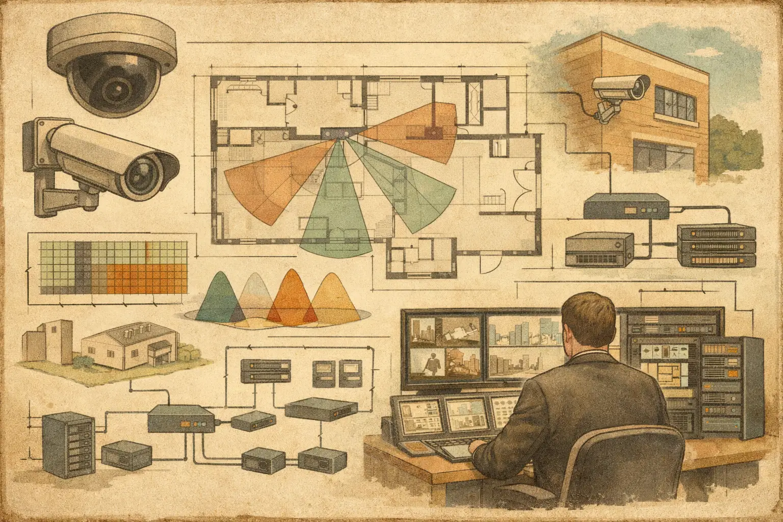
A UK CCTV planning guide should begin before any camera is placed on a drawing. The first engineering question is not how many cameras a site needs, but what each camera must enable an operator, investigator, or security process to do. A wide overview of a lobby, for example, is not the same requirement as identifying a person at an entrance or reading activity at a loading dock.
This distinction drives the optical design, camera schedule, storage estimate, network load, mounting arrangement, and eventual review process. Treating CCTV as a symbol-placement exercise often creates drawings that look complete but cannot demonstrate usable coverage where it matters.
Define the operational requirement first
Start with a site survey, current architectural drawings, and a written security brief. Review the areas that create risk or require observation: property boundaries, pedestrian entrances, vehicle gates, reception areas, corridors, stairwells, loading zones, parking areas, and critical equipment rooms. Then convert broad statements such as "cover the entrance" into a measurable operational objective.
DORI provides a useful framework for this discussion: detection, observation, recognition, and identification. The required level depends on the scene and process. A camera monitoring whether someone has entered a fenced area may need detection coverage over a broad zone. A controlled doorway may require recognition or identification coverage at a defined crossing point. These are different design targets, not interchangeable labels.
Pixel density, commonly expressed as pixels per meter (PPM), should be assigned against the required task and project specification. DORI values and PPM calculations are planning inputs, not proof of real-world performance. Lighting, motion, compression, lens quality, camera processing, scene contrast, and installation tolerances can materially affect the delivered image.
Establish a reliable drawing base
Coverage analysis is only credible when the drawing is correctly scaled. Import the latest floor plan, site plan, or reflected ceiling plan, then calibrate scale using a known, verified dimension. A scale error affects every downstream result: camera distances, field-of-view dimensions, pixel-density zones, cable routes, and equipment quantities.
The drawing should also represent the geometry that changes sight lines. Build or review walls, partitions, doors, glazing where relevant, columns, shelving, machinery, gates, and external structures. A camera cone drawn across a plan without occlusion modeling can imply coverage through a wall or around a column. That may be visually persuasive, but it is not an engineering result.
For complex premises, coordinate the CCTV model with the latest architectural issue and record its revision reference. A late change to a partition, ceiling bulkhead, gate position, or landscape feature can create a blind spot or invalidate a previously suitable mounting location.
Verify the scene, not just the plan
Plans rarely capture every constraint. A site walk should test the conditions that affect camera placement: available mounting points, final ceiling heights, lighting direction, reflective surfaces, seasonal vegetation, vehicle movements, and access for installation and maintenance. In outdoor locations, check whether proposed poles, façades, or structures can physically support the intended camera and cabling arrangement.
Where a design relies on a particular view through an opening, gate, or doorway, document that dependency. Open doors, roller shutters, and parked vehicles can all change the effective field of view.
Select cameras from optical inputs
A useful camera specification begins with technical parameters rather than a manufacturer name. Define resolution, sensor size, focal length or varifocal range, mounting height, direction, tilt, and expected scene distance. These inputs determine the field of view and how available pixels are distributed across the monitored area.
A wider field of view covers more space but reduces pixel density at distance. A narrower focal length can improve detail in a target zone but may introduce gaps beside it. Higher resolution can increase available detail, but it also affects bandwidth, recording storage, and sometimes low-light behavior. There is no universally correct combination.
Mounting height requires similar judgment. Raising a camera may reduce tampering risk and widen the view, but it can increase the angle to faces and obscure features beneath soffits or canopies. Excessive downward tilt may provide useful situational awareness while weakening facial detail at the point where identification is required. Use the elevation and target-plane geometry, not only the plan view, to assess the result.
For each camera, record the design intent in a schedule: location reference, camera type, mounting height, focal length, direction, tilt, resolution, target area, and required DORI or PPM criterion. This creates traceability between the operational brief and the installed system.
Review coverage, blind spots, and overlap
Once cameras are positioned, assess the combined coverage layer rather than reviewing each field of view in isolation. Identify blind spots at entrances, corners, transition areas, and behind fixed obstructions. Then check whether overlaps are intentional.
Coverage overlap can be valuable at critical points. One camera may provide a contextual overview while another provides a tighter view at an access-controlled door. Overlap can also preserve observation if a temporary obstruction affects one view. However, unnecessary overlap consumes camera channels, switch capacity, storage, and review time without necessarily improving the security outcome.
A practical review should distinguish between a visible area and a usable area. A location may sit inside a camera cone but fail to achieve the specified pixel density. Likewise, a calculated view may be clear on a drawing yet be compromised in the field by glare, backlighting, headlights, shadows, or a change in the operational layout.
Use calculated coverage to identify design issues early, then verify critical views during commissioning under representative operating conditions. The design model supports a disciplined decision; it does not replace installation testing.
Coordinate network topology and recording capacity
CCTV planning should run in parallel with ICT coordination. A camera schedule without a network topology is incomplete, particularly on multi-floor, campus, or outdoor projects. Establish the intended path from camera to edge switch, communications room, recording platform, and client viewing environment.
Calculate expected bandwidth from the intended resolution, frame rate, compression settings, scene activity, and recording policy supplied for the project. Avoid relying on a single generic bitrate figure. A quiet corridor and a busy vehicle entrance can produce substantially different loads with comparable camera hardware.
Review Power over Ethernet capacity, uplink loading, switch locations, cabinet space, fiber routes where needed, and resilience requirements identified by the project team. The recorder and storage design should be based on the required retention period, camera count, recording profile, and operational configuration. These figures should be reviewed against the selected manufacturer datasheets and the final system settings.
Keep physical and logical design aligned
The cable route needs the same attention as the field of view. Confirm approximate route lengths, containment availability, penetrations, external protection, and separation requirements with the relevant disciplines. Camera IDs should remain consistent across drawings, schedules, network diagrams, and reports. A mismatch between CAM-23 on a floor plan and Camera 23 in a recorder list is a small documentation error that can become a major commissioning delay.
Address UK project requirements carefully
UK projects may involve client standards, planning conditions, local authority requirements, privacy expectations, employment considerations, and sector-specific obligations. The applicable requirements depend on the site, use case, organization, and jurisdiction. They should be confirmed by the project owner and qualified legal, security, privacy, and technical professionals.
From a design perspective, document the purpose of each camera and avoid collecting a wider view than the security objective requires. Pay close attention to property boundaries, public-facing areas, neighboring windows, welfare spaces, and other sensitive locations. Privacy masking, access permissions, retention settings, signage, and operational procedures are system and governance decisions that must be specified and reviewed separately from a camera coverage drawing.
Do not present calculated DORI coverage or a camera layout as evidence of regulatory approval. A technical design can support a review process, but it cannot itself guarantee compliance, authority acceptance, or installed performance.
Produce a coordinated design package
The final deliverable should let an installer, reviewer, client, and ICT stakeholder understand the same design without reconstructing the assumptions. At minimum, issue calibrated plans with camera locations and IDs, field-of-view and coverage analysis, the camera schedule, key elevations or mounting details, network topology, cable-routing assumptions, and a record of open coordination items.
CCTV Design Tool Online can bring these elements into one persistent browser-based workspace: calibrated drawings, physical geometry, camera parameters, occlusion-aware fields of view, DORI and pixel-density analysis, network planning, and structured technical reports. The value is not simply faster camera placement. It is a clearer chain from security objective to design input, calculated output, review comment, and revised deliverable.
Before release, conduct a formal design review with the people responsible for security operations, architecture, electrical installation, and ICT infrastructure. Ask a direct question for every critical scene: what task must this camera support, at what location, under what conditions, and how will that result be verified on site? That question keeps the project focused on evidence rather than camera count.