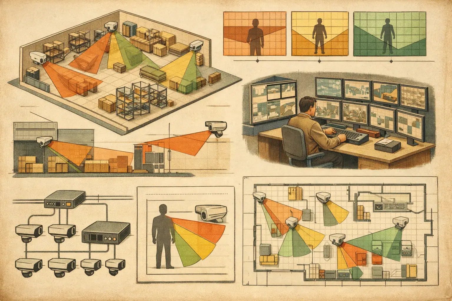
A warehouse surveillance redesign example is most useful when it starts with an operational failure rather than a camera count. In this scenario, a distribution warehouse has cameras at entrances, loading docks, and main aisles, but incident reviews repeatedly reveal the same issue: footage shows movement without providing enough detail to identify a person, read a pallet label, or confirm which loading-bay door was used. The redesign task is not simply to add cameras. It is to define what each camera must achieve, test coverage against the actual building geometry, and produce a coordinated design that installation and ICT teams can work from.
The starting condition: coverage that looks adequate
Assume a single-story warehouse with racking aisles, a receiving area, outbound loading docks, a packing zone, a secure cage, and staff access doors. The original system uses wide-angle fixed cameras mounted high on perimeter walls and columns. On a simple plan, the camera cones appear to cover most open floor space.
The problem becomes clear when the design is reviewed against real surveillance objectives. A wide field of view may provide detection of activity across an aisle, yet produce insufficient pixel density for recognition or identification at the far end. Tall racking creates occlusion. Dock doors introduce strong changes in lighting. Forklifts, pallets, and temporary staging areas change sightlines throughout the day.
The redesign begins by separating general observation from evidential or operational requirements. In this example, the project team defines four primary objectives: detect movement at perimeter access points, recognize staff and visitors entering restricted zones, identify persons at the secure cage and staff entrances, and observe loading activity with usable detail around dock doors and vehicle interfaces.
Warehouse surveillance redesign example: establish the design inputs
Before moving cameras, import the current floor plan and calibrate its scale using a known dimension from the architectural drawing or a verified site measurement. Scale calibration is not a presentation step. If the drawing scale is wrong, field-of-view distances, camera spacing, pixel-density results, and cable route estimates can all be misleading.
Next, review the physical geometry. Exterior walls, internal partitions, columns, racking blocks, dock doors, office glazing, and secure-cage fencing should be represented as accurately as the available drawings allow. Racking deserves particular attention. A warehouse plan may show aisles but omit rack height, end-cap protection, or temporary storage zones that materially affect sightlines.
For each existing camera, record the available technical inputs: mounting height, direction, tilt, resolution, sensor size, focal length, and whether the device is fixed or adjustable. If the installed model is unknown, do not substitute assumed manufacturer performance. Use confirmed specifications where available, or flag the camera as requiring site verification.
The output at this stage is a scaled, reviewable base drawing with existing camera locations and known physical obstructions. It gives the project team a reliable reference point for deciding whether a weakness comes from camera position, optics, image detail, geometry, lighting conditions, or a combination of these factors.
Review DORI and pixel density by task
A redesign should not apply one PPM target across the whole warehouse. DORI provides a practical framework for matching image detail to a surveillance purpose: detection, observation, recognition, and identification. The appropriate target depends on the defined task, project requirements, and the conditions under which the image will be used.
In this example, the central aisle cameras may only need broad detection and observation because their purpose is to show movement and workflow direction. The secure cage entrance has a higher requirement because the team needs to distinguish individuals entering or leaving the controlled area. The dock-door cameras need enough usable detail at the threshold to associate a person, vehicle movement, or pallet-handling event with a specific bay.
Calculate pixel density across each field of view, not only at the camera location or centerline. A wide-angle camera mounted at 26 feet may cover a large portion of a loading area, but its PPM will decline with distance and field width. If the required detail occurs only near the dock threshold, the design may use a dedicated tighter-view camera for that task while retaining the wider camera for situational awareness.
This is a common redesign decision: one camera cannot always provide both broad context and high-detail coverage. Adding a second purpose-specific view can be more defensible than forcing a single camera to cover an overly wide scene with inadequate detail.
Test occlusion rather than drawing idealized cones
The original design showed aisle coverage by drawing camera cones through racking. In practice, those cones did not represent visible space. A camera at the end of a long aisle could observe a clear path when the aisle was empty, but pallet overhangs, forklift traffic, and cross-aisle storage interrupted the view.
Review line of sight against modeled walls and obstructions. At a minimum, assess the view at expected rack height and camera mounting height. Then identify the areas hidden behind rack ends, columns, dock equipment, and open doors. A camera cone without occlusion analysis may be visually persuasive while offering little engineering value.
In the redesigned layout, cameras are repositioned to view along selected aisles from lower-angle cross-aisle locations rather than relying solely on long views from perimeter walls. This reduces blind spots at rack intersections. However, it introduces a trade-off: more cameras may be needed, and each added device requires power, network capacity, storage consideration, maintenance access, and documentation.
Coverage overlap is added deliberately at critical points rather than spread uniformly. For example, the secure cage entrance is visible from both an approach camera and a closer access-point camera. The overlap provides context from one view and higher-detail imagery from the other. It also reduces the risk that a person is obscured by an open door, another person, or a temporary obstruction at the entrance.
Reposition cameras by operational zone
The redesign can now be organized by zone rather than by generic camera type. At loading docks, a wide contextual camera is positioned to observe vehicle approach and dock activity, while a narrower view covers the door threshold and handoff area. The camera direction and tilt are adjusted so the critical target zone sits within the portion of the field of view that meets the required pixel density.
In racking aisles, the team uses selected cross-aisle cameras to observe intersections and high-value movement paths. It does not attempt to identify every person at every point along every aisle from one high-mounted device. Where identification is genuinely required, such as a controlled-access door, the design creates a dedicated identification zone with a defined target distance and a suitable focal length.
At staff doors, mounting height must balance tamper resistance, facial angle, and field of view. A very high camera may be harder to reach but can produce an unfavorable downward angle for facial detail. A lower protected mounting position, combined with appropriate tilt and lens selection, may better support the intended task. The final choice depends on the site conditions, risk profile, and available mounting infrastructure.
Coordinate the network topology before issuing the design
Camera placement changes affect more than coverage. The revised design should identify likely network cabinet locations, cable pathways, PoE switch capacity, uplink requirements, and any practical limits on copper runs. A camera moved to a rack intersection may solve an occlusion problem but create a difficult cable route through an active operational area.
Create a camera schedule that ties each device to its zone, purpose, mounting height, direction, focal length, resolution, calculated coverage result, and network connection point. This traceability matters during procurement, installation, commissioning, and later modifications. It also makes review easier when architects, warehouse operations teams, security managers, and ICT personnel need to assess the same design decisions from different perspectives.
A browser-based workspace such as CCTV Design Tool Online can bring calibrated plans, camera parameters, field-of-view calculations, DORI review, obstruction-aware geometry, and reporting into one persistent project record. The calculated output still requires professional review against site conditions, approved equipment data, lighting, installation constraints, and any jurisdiction-specific requirements.
Issue a deliverable that supports review and installation
The completed redesign package should show more than camera icons. It should include the calibrated plan, camera locations, viewing directions, field-of-view coverage, identified blind spots, relevant overlap zones, camera schedule, and network planning assumptions. Where a design decision involves a limitation, state it clearly. For example, a camera may provide detection along a full aisle but recognition only within a defined near-field area.
This level of documentation prevents a familiar site dispute: a camera was installed where the drawing indicated, yet it cannot perform the task someone assumed it would perform. Stating calculated intent and coverage boundaries gives installers a clearer target and gives reviewers a basis for asking the right questions before work begins.
A warehouse redesign is strongest when every camera has a stated operational purpose, a verified position on a calibrated drawing, and a coverage result that can be explained. That discipline turns a collection of devices into a design that can be reviewed, installed, tested, and improved with far less ambiguity.