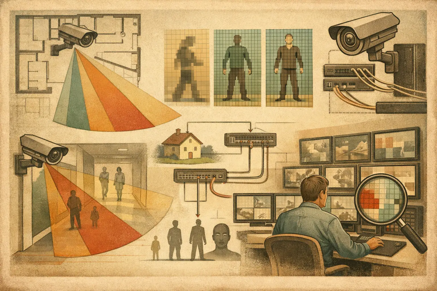
A camera can show a doorway clearly on a floor plan yet provide too little image detail to recognize the person using it. That gap is exactly why security designers ask, what is CCTV PPM? PPM turns a broad coverage drawing into a measurable design question: how many image pixels represent each meter of the scene at the point that matters?
For consultants, installers, and project reviewers, PPM is not a substitute for camera testing or a regulatory requirement by itself. It is a practical pixel-density measure that helps connect camera resolution, lens selection, field of view, and operational objectives before equipment reaches the site.
What Is CCTV PPM?
CCTV PPM means pixels per meter. It describes the number of horizontal image pixels available across one meter of real-world scene width at a defined location. Higher PPM generally means more usable subject detail. Lower PPM means the camera covers a wider area, but each person, object, or vehicle occupies fewer pixels.
The measurement is scene-specific, not a fixed property of the camera. A 4K camera does not inherently deliver a particular PPM value. Its pixel density changes with the width of the observed scene, which is affected by focal length, sensor size, mounting position, camera direction, tilt, and the distance or plane being assessed.
This distinction matters on real projects. A wide-angle camera may provide valuable situational awareness across a lobby, parking area, or perimeter approach. It may not provide sufficient detail at a distant gate, reception desk, or pedestrian entrance. In many cases, the correct answer is not to replace the wide camera, but to add a second camera with a narrower field of view for the specific task.
How CCTV PPM Is Calculated
At a defined plane, the basic calculation is straightforward:
PPM = horizontal camera resolution / real-world scene width in meters
If a camera produces 3,840 horizontal pixels and its field of view is 12 meters wide at the required observation line, the calculated density is 320 PPM.
The calculation only has value when its inputs represent the actual design condition. Use the horizontal resolution of the configured video stream, not simply a marketing label such as 4K or 8 MP. Then measure the real scene width at the target location, not the overall width of the floor plan or the widest point of the camera cone.
For a camera aimed across a vertical wall or access point, this can be relatively direct. For a camera looking down at an angle across a floor, pixel density varies substantially from the near edge to the far edge. The far boundary may be the limiting point because the same image width represents a much wider physical area there. A single PPM figure can therefore conceal a weak zone unless the design evaluates relevant distances or target planes separately.
Calculated PPM also does not account for every factor that affects usable evidence. Motion blur, poor lighting, wide dynamic range limits, focus accuracy, compression, frame rate, lens distortion, dirty housings, and scene obstructions can reduce actual performance. Treat PPM as a transparent design calculation, then validate critical views through commissioning and representative site conditions.
CCTV PPM and DORI: Related but Different
PPM is the measurement. DORI is a structured way to relate pixel density to a surveillance objective: detect, observe, recognize, or identify. Used together, they make a design review more meaningful than a camera cone alone.
Common DORI planning values are often expressed as 25 PPM for detection, 62.5 PPM for observation, 125 PPM for recognition, and 250 PPM for identification. These figures are widely used as engineering reference points, but they are not automatic legal, contractual, or authority requirements. The project brief, applicable jurisdiction, risk assessment, and client operating procedure must define the required outcome.
| Objective | Typical planning intent | Common reference pixel density | | --- | --- | --- | | Detect | Establish that a person or object is present | 25 PPM | | Observe | See characteristic activity and movement | 62.5 PPM | | Recognize | Recognize a familiar person | 125 PPM | | Identify | Distinguish an unknown person with high detail | 250 PPM |
The terms need careful use. Recognition is not the same as identification, and neither is guaranteed by a calculated pixel density. For example, identifying a person may depend on face angle, lighting direction, headwear, movement, camera focus, image processing, and the quality of the recorded stream. If a project uses analytics, the relevant performance criteria should be tested against the selected camera, settings, and scene rather than inferred from PPM alone.
Why Lens Choice Changes PPM More Than Resolution Alone
Resolution matters, but it is only one side of the calculation. A higher-resolution camera covering an overly wide scene can still deliver inadequate pixel density at the target. Conversely, a lower-resolution camera with an appropriately selected focal length may meet the operational objective within a constrained access corridor.
Increasing focal length narrows the field of view. At the same target plane, fewer meters fit across the image width, so PPM rises. The trade-off is reduced contextual coverage and a greater risk of blind spots outside the narrower view. Sensor size also affects field of view: the same focal length does not frame the same scene on every sensor format.
Mounting height and tilt require equal attention. Raising a camera can reduce vandalism risk and improve general oversight, but a steep angle can make faces less useful and make ground-plane PPM uneven. Walls, shelving, vehicle bays, vegetation, doors, and other geometry can also create occlusion. Pixel density in an area hidden behind an obstruction has no operational value.
A Practical PPM Workflow for CCTV Design
Start by defining what the camera must achieve at each critical point. A loading-dock overview, an emergency exit, a cashier position, and a vehicle gate may all have different DORI objectives. Avoid applying identification-level density to every square foot by default. That approach can create unnecessary camera counts, excessive storage demand, and difficult network topology without improving the actual security outcome.
Calibrate the drawing before measuring coverage
Import the floor plan or site drawing and set scale calibration from a verified reference dimension. An incorrect scale changes field-of-view dimensions, camera distances, coverage areas, and PPM results together. A visually convincing design built on an uncalibrated plan is still unreliable for engineering review.
Configure the camera from technical inputs
Set the camera's horizontal resolution, sensor size, focal length or varifocal range, mounting height, direction, and tilt. Use verified manufacturer data for the proposed model where available. For early-stage design, clearly label assumed values so that later substitutions can be reviewed rather than silently changing the result.
Check PPM at the task location, not only the camera edge
Place measurement lines or target zones at doors, transaction points, lanes, and other areas where an operational decision will be made. Review the field of view against walls, openings, and physical obstructions. Then inspect whether the intended PPM is achieved where people are expected to stand or move, including the farthest relevant point in a corridor or approach path.
Record the result in a reviewable deliverable
A camera schedule should state more than the camera model and location. Record the intended purpose, lens configuration, mounting details, target area, calculated PPM or DORI result, and any limitations such as expected occlusion or a pending site verification. This creates traceability when architects revise a layout, a contractor changes mounting positions, or a project owner asks why an additional camera is necessary.
A browser-based workspace such as CCTV Design Tool Online can keep calibrated drawings, physical geometry, field-of-view analysis, DORI coverage, network planning, and report outputs connected. The result remains a calculated design model, so qualified review and on-site validation are still required for critical views.
Common PPM Design Errors
One frequent error is calculating PPM from the camera's maximum coverage width instead of the required target width. Another is using total megapixels rather than horizontal pixel resolution. A 16:9 camera's horizontal resolution, not its overall pixel count, is what belongs in the standard horizontal PPM calculation.
Design teams also sometimes assume that one camera must satisfy every purpose. A camera positioned for broad detection may be poorly placed for recognition at an entrance. Separating overview and detail functions often produces a clearer design and makes the rationale easier to explain.
Finally, do not treat an unobstructed cone as verified coverage. Recheck the model when a wall moves, a door swings into view, a rack is added, or the final mounting height changes. Small geometry changes can alter occlusion and pixel density at the most critical locations.
The useful question is not whether a camera sees an area. It is whether the calculated pixel density, viewpoint, and scene conditions support the specific action the operator, investigator, or site team needs from that camera.