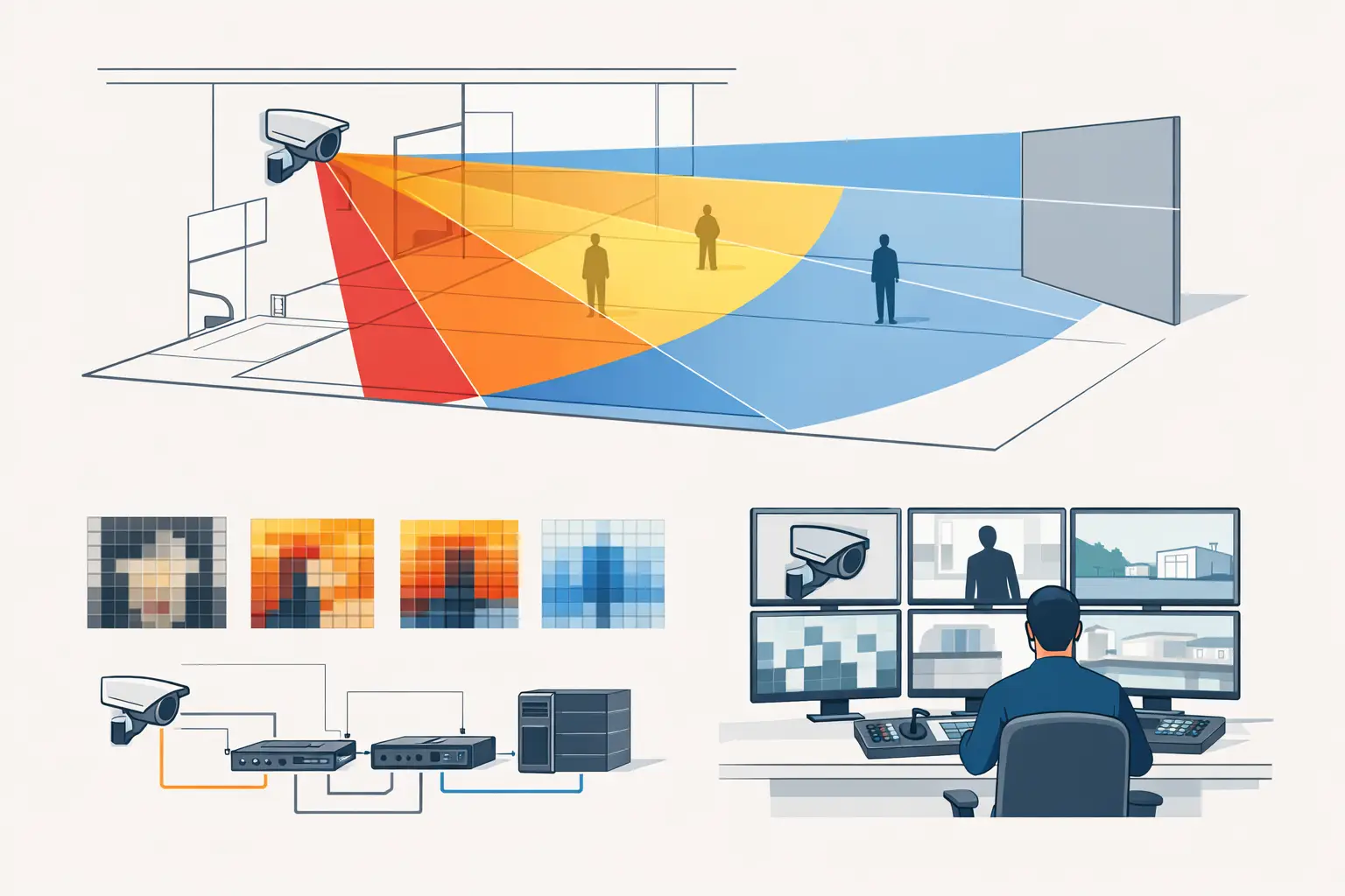
A camera icon on a floor plan is not evidence that a scene can be monitored effectively. The practical question is what the camera must allow an operator, investigator, or system to do at each location. That is where the question, what is DORI criteria, becomes central to CCTV design.
DORI translates a surveillance objective into a measurable pixel-density requirement. Rather than asking whether a camera can “see” an area, it asks whether it provides enough detail at the relevant distance to detect activity, observe characteristics, recognize a familiar person, or identify an unknown person. This distinction affects camera location, focal length, resolution, field of view, mounting height, and the number of cameras required.
What Is DORI Criteria in CCTV Design?
DORI stands for Detect, Observe, Recognize, and Identify. It is a framework used to define the level of image detail required for a surveillance task. The criteria are commonly expressed in pixels per meter, or PPM, measured across the target area.
DORI is widely associated with IEC 62676-4 application guidance and its European adoption, EN 62676-4. Project teams should verify the exact edition, contractual specification, and jurisdictional requirements that apply to their project. DORI is a useful engineering basis for coverage design, but it is not by itself proof of regulatory compliance or installed-system performance.
The commonly referenced thresholds are 25 PPM for detection, 62.5 PPM for observation, 125 PPM for recognition, and 250 PPM for identification. These are design benchmarks, not a promise that every recorded image will produce the same operational outcome. Lighting, motion blur, compression, camera setup, scene contrast, and occlusion still influence real-world results.
The Four DORI Levels
Detect - 25 PPM
Detection answers a basic question: is there a person, vehicle, or other object present in the scene? At approximately 25 PPM, a viewer may distinguish an object from its background and see movement or occupancy, but cannot reliably determine who the person is.
Detection coverage is appropriate for broad-area awareness, such as a perimeter approach, an open yard, or a large parking area. A wide field of view may be useful here because the requirement is presence, not facial or fine-detail evidence.
Observe - 62.5 PPM
Observation provides more visual context. A viewer may assess general activity and distinguish broad characteristics such as clothing color, direction of travel, or an object being carried. It is still not intended to establish identity.
This level can support operational monitoring where a security team needs to understand what is happening in a zone. It is often useful at building approaches, loading areas, corridors, and public circulation spaces, depending on the project risk assessment.
Recognize - 125 PPM
Recognition is intended to let a viewer determine whether an individual is someone already known. For example, a site team may compare a live or recorded image with a known staff member, contractor, or repeat visitor.
Recognition requires a substantially tighter field of view than detection. A camera that meets 125 PPM at a doorway may fall below that level only a few meters beyond it, particularly when using a wide-angle lens. The relevant question is therefore not whether the camera reaches the doorway, but where the 125 PPM contour falls across the access path.
Identify - 250 PPM
Identification is the highest standard DORI level. It supports distinguishing an unknown individual with sufficient detail for identification under suitable conditions. It is commonly considered at controlled entrances, reception points, turnstiles, cash-handling areas, and other locations where the project brief requires a clear identity-focused view.
An identification target must be designed around the likely position, direction, and height of the person being captured. A 250 PPM calculation across an open floor area may have limited value if the subject is backlit, looking away from the camera, obscured by a door frame, or moving quickly through the scene.
How Pixel Density Is Calculated
At a basic level, pixel density is calculated by dividing the available horizontal image pixels by the real-world scene width at a given distance:
PPM = horizontal image resolution ÷ scene width in meters
Consider a camera producing 3840 horizontal pixels. If its field of view is 15.36 meters wide at the target plane, the calculated density is 250 PPM. If the same camera covers a 30.72-meter-wide scene, the density falls to 125 PPM.
The calculation shows why resolution alone does not define usable detail. A high-resolution camera can still provide only detection-level coverage if its field of view is too wide. Conversely, a camera with lower resolution may meet identification requirements over a narrow, controlled passage when paired with an appropriate focal length.
For design purposes, the width of the scene changes with distance and lens geometry. Sensor size, focal length, camera direction, mounting height, tilt, and the angle between the camera and target plane all affect the result. A simple cone drawn on a plan cannot reliably communicate DORI performance unless those inputs are modeled.
DORI Is Not the Same as Camera Resolution
A common specification error is to select a camera based on megapixels and assume that image detail will follow. Megapixels describe the number of pixels available in the image. DORI describes the pixel density delivered at a specific point in the scene.
For example, a 4K camera with a short focal length may provide wide detection coverage across a lobby. The same camera with a longer focal length may deliver recognition or identification along a narrow entrance route. Neither setup is automatically better. The correct choice depends on the surveillance objective and the operational geometry.
This is also why digital zoom should be treated carefully during design review. Enlarging a recorded image does not create missing scene detail. The source image must contain sufficient pixels on the target at capture time.
Applying DORI to a CCTV Layout
Start with the activity or evidence requirement, not the camera model. An exterior fence line may need detection. A vehicle gate may need observation of vehicle activity and recognition of an approaching driver. A staff entrance may need identification at the credential-check position. These are different design objectives and often require different camera views.
Next, establish accurate geometry. Import and calibrate the floor plan, then review walls, doors, glazing, columns, racking, landscaping, and other physical obstructions. A calculated pixel-density zone that extends through a wall is not usable coverage. Likewise, a view that appears clear on a plan may be blocked by a door in its open position, a parked vehicle, or a change in floor level.
Then position the camera using realistic installation inputs. Set the mounting height, direction, tilt, sensor size, resolution, and focal length. Review field of view and PPM zones together. This makes it easier to see where a camera changes from identification to recognition, or from observation to detection, as the target moves farther from the lens.
Finally, assess the coverage as a system. A site may need overlapping views where one camera provides broad situational awareness and another provides a tighter identity view. Overlap is not automatically wasteful. It can provide context, reduce blind spots at transitions, and support review when one view is obstructed. However, unnecessary overlap can increase camera count, storage, switching capacity, and network demand.
Factors That Can Reduce Field Performance
DORI calculations are based on geometry and image resolution, but field performance depends on additional conditions. At minimum, the design review should consider:
- Lighting level and direction, including glare, backlight, reflections, and night illumination.
- Motion speed, shutter configuration, and resulting motion blur.
- Video compression, stream settings, and recorder throughput.
- Target angle, face orientation, headwear, masks, and physical occlusion.
- Installation tolerances, vibration, lens adjustment, dirt on the housing, and future scene changes.
These factors do not make DORI less useful. They show why DORI should be treated as a traceable design calculation rather than a substitute for commissioning, scene testing, and qualified engineering review.
Using DORI for Better Project Documentation
DORI becomes especially valuable when it is recorded consistently. A camera schedule should state the intended purpose of each view, the modeled lens and resolution, the target area, and the required DORI level at that area. Floor plans should make the coverage boundaries understandable to installers, reviewers, and project owners.
A browser-based workflow such as CCTV Design Tool Online can bring calibrated plans, camera parameters, physical geometry, DORI coverage, blind-spot review, and report outputs into one design workspace. The benefit is traceability: when a focal length, camera position, or wall changes, the design team can review the downstream effect on coverage and documentation rather than relying on disconnected drawings and manual calculations.
Before finalizing a layout, identify the few locations where evidence quality matters most and validate their DORI requirement against the real scene, installation constraints, and project brief. That discipline turns camera coverage from a visual assumption into an engineering decision.