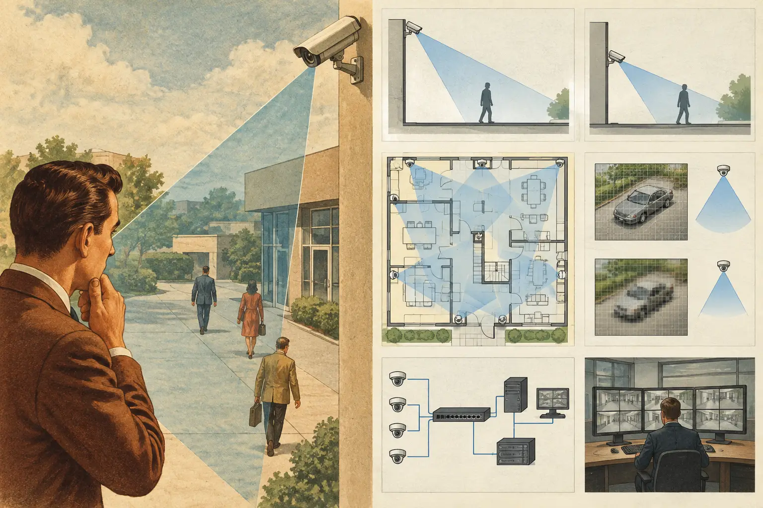
A camera can appear to cover an entire lobby, loading yard, or corridor on a floor plan and still fail the operational objective because it is mounted at the wrong level. That is why camera height matters: mounting height changes the viewing angle, effective target distance, pixel density, occlusion risk, and the usefulness of recorded detail. It is not a drawing annotation to add after camera locations are agreed. It is a primary design input.
For security consultants, integrators, and project teams, the practical question is not simply, "How high can the camera be mounted?" It is, "At what height can this camera deliver the required result at the relevant target area, while remaining installable and serviceable?" The answer depends on the scene geometry, camera specification, focal length, sensor size, resolution, tilt, lighting conditions, physical obstructions, and required DORI objective.
Why Camera Height Matters for CCTV Coverage
Camera height affects both what the camera can see and what it can prove. Raising a camera generally expands the visible ground area, particularly when the camera is tilted downward. That can be useful for broad situational awareness, perimeter observation, and monitoring activity across an open space. However, the larger visible area is not automatically better coverage. The scene is viewed at a steeper angle, and people, vehicles, doors, faces, license plates, and other targets may occupy fewer useful pixels or be seen from an unsuitable perspective.
A lower mounting position can improve the horizontal view of a target and often provides more usable facial detail at entrances, transaction points, or access-controlled doors. It may also create a more favorable angle for observing a person approaching the camera. The trade-off is greater vulnerability to tampering, a narrower visible floor area, and potentially more obstructions from furniture, vehicles, landscaping, or other people.
Height therefore needs to be assessed alongside direction and tilt. A camera mounted at 16 feet and tilted sharply down may show a large floor area but provide poor detail at the far edge of its field of view. The same camera mounted at 10 feet with a different focal length and a more controlled viewing direction may better support identification at a doorway. Neither arrangement is universally correct. The design objective determines the appropriate geometry.
Height Changes Field of View Geometry
A camera's field of view is governed by sensor size, focal length, and distance to the scene. Mounting height introduces a vertical component to that distance. When a camera looks down at a target, the optical path is the slant range, not simply the horizontal distance shown on a floor plan.
For example, a target positioned 20 feet from the wall below a camera may be substantially farther away in optical terms if the camera is mounted high above it. As mounting height increases, the slant range increases. This can reduce pixel density at the target, even where the two-dimensional plan suggests the target is within a reasonable coverage radius.
Tilt also changes how image resolution is distributed across the ground plane. With a steep downward angle, the near ground area may consume a significant part of the image while distant areas appear compressed. This is a common reason why a camera cone drawn in a CAD layer can look adequate while the actual image delivers weak detail where it is needed. A field-of-view calculation should represent the camera's mounting point, direction, tilt, and the relevant target plane, not only a flat wedge projected over a plan.
The effect on PPM and DORI
Pixel density, often expressed as pixels per foot or pixels per meter, provides a more traceable way to evaluate whether a target area has enough image detail for its intended purpose. DORI - detection, observation, recognition, and identification - provides a structured language for defining that purpose.
Mounting a camera higher does not change its native resolution. It does change how those available pixels are spread across the viewed scene. If the field of view becomes wider at the target area, fewer pixels may cover a person or object. If the target is farther away by slant range, pixel density may also decline.
DORI values are calculated design indicators, not guarantees of operational outcome. Real performance can be influenced by focus accuracy, compression, motion blur, lighting, scene contrast, installation tolerances, and manufacturer-specific image processing. Still, checking PPM and DORI at the actual target location is far more defensible than selecting a camera height by rule of thumb alone.
Occlusion Is a Vertical Design Problem
Most coverage reviews begin with walls, partitions, and doors. Those are essential, but many blind spots are created by objects below the camera line rather than by full-height walls. Racking, parked trucks, shelving, canopies, trees, suspended signs, turnstiles, cubicles, and even crowds can block a camera's view depending on mounting height and tilt.
A high camera may see over low furniture and pedestrian traffic, which is useful in open offices, retail spaces, warehouses, and public areas. Yet mounting it too high can place beams, roof structure, light fittings, or signage directly into the field of view. In external locations, a camera may clear a fence but still be affected by tree growth or vehicle roofs at the critical observation angle.
The relevant test is line of sight from the proposed camera location to the target area. A camera icon and coverage wedge alone cannot verify this. The design should include modeled walls and relevant physical geometry, with object heights where they materially affect visibility. This is especially important where the project requires a view through openings, across gates, over a reception desk, or along a vehicle route.
Mounting Height Must Match the Operational Scene
Entrances illustrate why a single standard mounting height is rarely sufficient. A camera intended to observe general movement through a lobby can be positioned for broad coverage. A camera intended to support recognition or identification at a controlled door needs a more deliberate target view. Excessive height can produce the top-of-head effect, where the camera captures clothing and head shape but limited facial detail.
In a warehouse, a high mounting position may be appropriate for monitoring aisles and loading activity, provided racking geometry and target distances are modeled. A second camera at a lower or more targeted position may still be needed for dock doors, personnel entrances, or vehicle identification. Trying to force one high-level overview camera to perform all tasks often leads to compromised results.
For perimeter applications, height must be balanced against tamper resistance, fence-line visibility, lighting, and the angle needed to observe an approaching subject. In parking areas, a camera high on a building facade can provide useful oversight but may not deliver the required detail on occupants or plates at every bay. The required evidence objective should be defined before the mounting detail is fixed.
A Practical Workflow for Setting Camera Height
Start by defining the target area and required outcome. State whether the camera is intended for detection, observation, recognition, identification, general oversight, incident review, or another documented project requirement. Then establish the target plane: a face at an entrance, a person on a walkway, a vehicle lane, a gate, or an elevated platform are not evaluated in the same way.
Next, import and calibrate the drawing so distances are meaningful. Place the proposed camera at an estimated mounting height, configure its resolution, sensor size, focal length, direction, and tilt, then review field of view and pixel density at the required target locations. Model walls and relevant obstructions before treating the result as a usable coverage assessment.
Test alternatives rather than assuming the first position is correct. A change of a few feet in mounting height, a modest adjustment in focal length, or a different camera location may improve the result more effectively than increasing resolution. Review overlap where cameras cover a critical route, but do not create overlap simply for its own sake. It should support continuity, reduce blind spots, or provide a second viewing angle for a defined risk.
CCTV Design Tool Online supports this engineering workflow by bringing calibrated plans, physical geometry, camera specifications, field-of-view visualization, DORI and pixel-density review, and technical reporting into one design workspace. The calculated output should then be checked against the actual site, coordinated with architectural and MEP constraints, and reviewed by qualified project professionals.
Verify the Designed Height Before Installation
A mounting height shown on a drawing can differ from the final installed height because of ceiling services, steelwork, facade details, access restrictions, or site changes. Small differences may be material where a camera is tightly designed around a doorway, aisle, or gate.
Before final acceptance, verify the physical mounting point, camera orientation, focal length setting, focus, and tilt. Confirm that the live image represents the intended target area under expected lighting conditions. This is not a substitute for the design stage; it is the necessary step that distinguishes calculated coverage from installed performance.
The most useful camera height is not the highest, lowest, or most convenient available point. It is the height that can be traced back to a defined security objective, a credible field-of-view calculation, clear line-of-sight review, and a site verification process that respects the real environment.