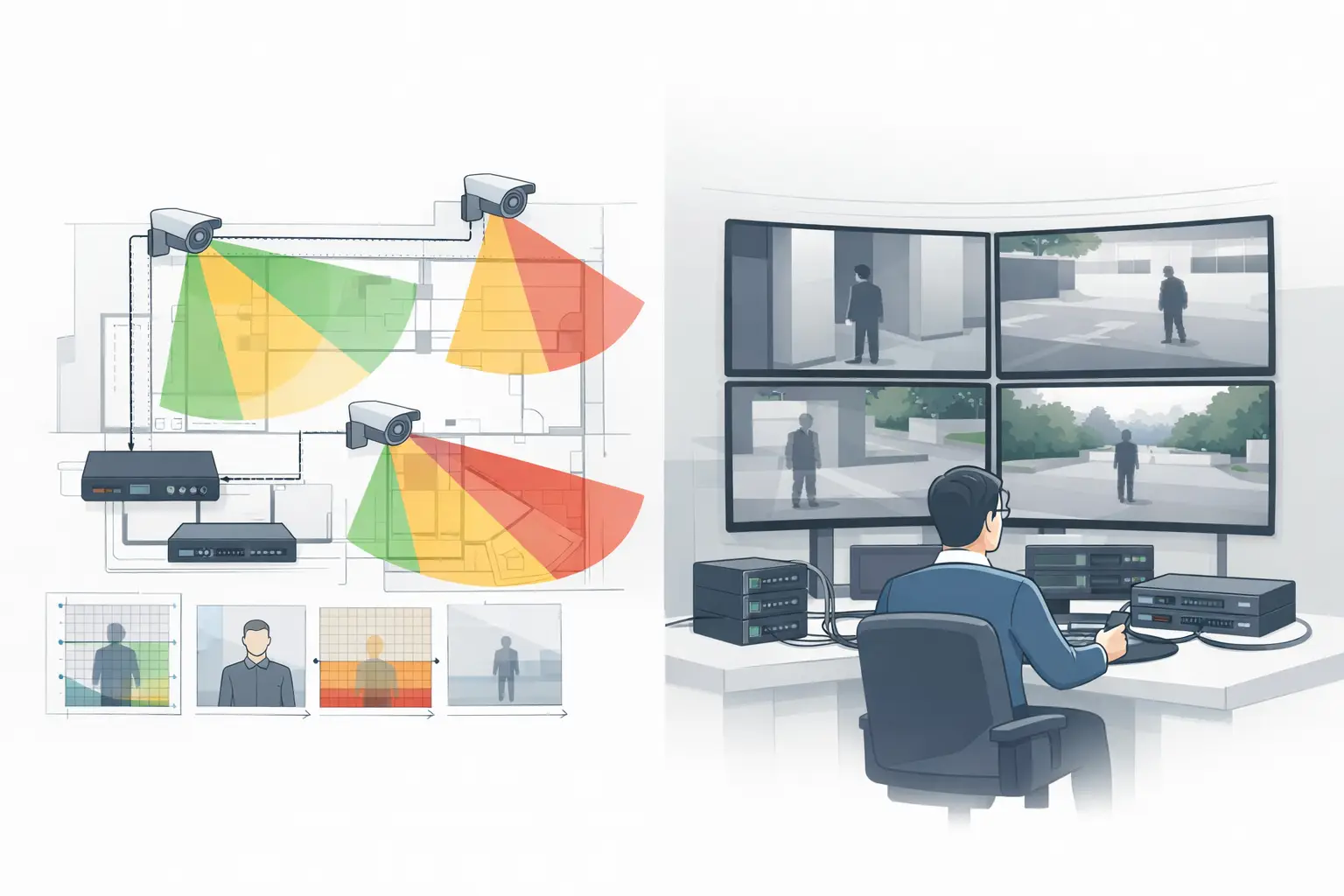
A camera symbol placed over a floor plan can look convincing long before it proves anything. That gap explains why do CCTV drawings fail on real projects: the drawing often communicates an intention to cover an area, while installation requires a camera to achieve a defined operational result through real geometry, optics, lighting, cabling, and coordination.
A CCTV drawing is not successful because every corridor, door, or perimeter line has a camera icon nearby. It is successful when the documented camera configuration can be installed, aimed, connected, and maintained while delivering the required level of detail at the intended target locations. The difference is an engineering workflow, not a drafting style.
Why Do CCTV Drawings Fail Before Installation?
Most failures begin when a plan is treated as a visual annotation rather than a technical model. A designer may place cameras based on intuition, use generic field-of-view cones, and issue a drawing without confirming scale, focal length, sensor size, mounting height, or pixel density. The result may be acceptable as an early concept, but it is not yet reliable for procurement, coordination, or construction.
The risk grows during project handover. The security consultant, installer, ICT contractor, architect, client, and reviewer may each interpret the same cone differently. One sees general observation of a lobby. Another expects identification at the reception desk. The installer finds a bulkhead, sign, or sprinkler main that prevents the shown mounting position. By then, a visually tidy drawing has become a source of rework.
This does not mean every concept drawing needs final construction-level detail. Project stage matters. Early layouts can appropriately show indicative coverage, provided their limitations are explicit. However, any drawing used to specify performance, approve equipment quantities, or coordinate installation should trace each camera position back to defensible inputs and stated coverage objectives.
Scale Calibration Errors Distort Every Calculation
An uncalibrated or incorrectly calibrated plan is one of the most damaging hidden problems in CCTV design. If the known reference dimension is wrong, every measured distance on the plan is wrong. A 10 percent scale error changes not only cable-route estimates but also field-of-view widths, target distances, and pixel-density calculations.
This commonly occurs when a PDF is exported at an unknown scale, a drawing is rasterized, or a floor plan has been resized in an image editor. It can also happen when teams use an architectural background that has changed after the CCTV layout was prepared. A camera cone may appear to reach a doorway on screen while the real doorway sits outside the usable optical coverage.
Import and calibrate the drawing against a verified dimension before placing or reviewing cameras. Then confirm that the calibrated reference still matches the latest architectural issue. Scale calibration is not administrative setup work. It is the basis for every subsequent calculation.
Generic Cones Ignore Camera Optics
A cone on a plan does not define a camera. The usable field of view depends on sensor size, focal length, aspect ratio, and the selected camera configuration. Two cameras labeled as 4K may produce materially different scene widths at the same mounting position because their sensor formats and lenses differ.
A wide-angle lens can show more of a room, but it spreads available pixels across a larger area. A longer focal length can provide greater pixel density at a gate or transaction point, but it narrows contextual coverage and may create blind spots to either side. Neither approach is automatically better. The right choice depends on the required task at each target location.
Camera resolution alone is not a coverage criterion. A design should review pixels per meter or pixels per foot at relevant distances and relate that result to the project requirement. DORI provides a useful framework for discussing detection, observation, recognition, and identification, but the required level must be established for the particular use case. A general lobby overview and a controlled-entry face capture point should not be evaluated as though they need identical detail.
Pixel Density Must Be Tested at the Target
A common drawing error is to calculate coverage at the centerline of the camera view, then assume the same result applies across the full image. In practice, target distance and pixel density vary across the field of view. A door at the edge of a wide image may have less usable detail than a person standing directly ahead.
Review the intended target plane, not merely the room outline. For doors, that could mean the approach path and face direction. For a vehicle entrance, it may involve the lane, stopping position, and likely angle of travel. The drawing should make the design intent visible enough that a reviewer can see what is being measured and why.
Walls, Glazing, and Site Elements Create Occlusion
Simple camera cones frequently pass through walls as though the building were empty. This is one of the clearest examples of a drawing that looks complete but cannot represent actual coverage. Physical geometry changes the result: walls block views, columns interrupt sightlines, shelving creates low-level shadows, and open doors can alter what a camera sees.
Glazing requires separate judgment. A camera may have a direct sightline through glass in a plan view, but reflections, glare, tinting, low-light conditions, and interior-to-exterior exposure differences can affect actual image performance. A line of sight is not a guarantee of usable video.
Mounting height and tilt matter as much as horizontal direction. A high ceiling mount may clear partitions, yet a steep tilt can reduce facial detail or obscure activity close to the wall below the camera. Conversely, a lower mount may improve the target angle but increase vulnerability to tampering or conflict with architectural finishes. These are project trade-offs that should be recorded rather than hidden behind a generic symbol.
A credible design models walls and relevant obstructions, then checks occlusion and blind spots from the configured camera position. It should also show intentional coverage overlap where continuity matters, such as circulation routes, lobby transitions, loading areas, or perimeter approaches. Overlap is useful when it supports a defined operational need; adding it everywhere can increase camera count, bandwidth, storage demand, and review complexity without improving the outcome.
Camera Schedules and Drawings Lose Synchronization
A technically sound layout can still fail when its documents disagree. Camera IDs on plans, schedules, elevations, bills of quantities, network diagrams, and reports must remain aligned through revisions. If one drawing shows CAM-17 as a fixed camera with a 2.8 mm lens and the schedule lists a varifocal model at a different location, installers and reviewers are forced to guess.
This issue is especially common when camera placement is managed in CAD, calculations in spreadsheets, scene views in image editors, and reports in a separate document. Each tool can be useful, but disconnected files create manual transcription points. A late lens change may never reach the coverage diagram. A revised room layout may not reach the cable schedule.
Use one controlled source of design data where possible, or establish a strict revision process across the document set. CCTV Design Tool Online supports this discipline by keeping camera parameters, physical geometry, field-of-view visualization, DORI and pixel-density review, network planning, and report outputs in a persistent workspace. The calculated result still requires professional review, but traceable inputs make inconsistencies easier to identify before issue.
Network and Installation Constraints Arrive Too Late
A CCTV drawing can be optically correct and still be impractical to build. Camera locations affect containment routes, PoE switch placement, uplink capacity, cabinet space, power resilience, and access for commissioning and maintenance. These constraints are sometimes left until after the coverage design is approved, when moving a camera may compromise the carefully calculated view.
Coordinate the security layout with architecture, electrical, ICT, fire protection, and ceiling services early. Confirm that the proposed mounting surface exists, that a cable path is feasible, and that access equipment can reach the device after handover. For exterior installations, consider the practical implications of poles, brackets, trench routes, wind exposure, and maintenance access. The exact solution will depend on site conditions and project requirements.
Network topology should develop alongside the camera layout. Resolution, frame rate, compression settings, scene activity, retention requirements, and recording architecture all affect bandwidth and storage estimates. A drawing cannot establish final network performance by itself, but it should provide the camera data and location logic needed for the network design to be checked.
Turn the Drawing Into a Reviewable Design
The best corrective action is to shift the review question from “Do we have cameras in the right places?” to “Can each camera demonstrate the required outcome?” That changes the design process.
Start with the latest verified floor plan and calibrate its scale. Define the security objectives by area, then configure each camera using known or proposed technical parameters: resolution, sensor size, focal length, mounting height, direction, and tilt. Model walls and relevant obstructions before assessing field of view. Review pixel density and DORI at actual target locations, not only at the widest visible edge of a cone.
Next, inspect blind spots, occlusion, and intentional coverage overlap. Coordinate mounting points and routes with the wider project team. Finally, generate a structured deliverable that ties camera IDs, views, calculations, assumptions, and network considerations together. If specifications or manufacturer data change, revise the model and reissue the affected documents under revision control.
Calculated coverage is design evidence, not proof of field performance. Final results can be affected by installed mounting position, lens selection, commissioning adjustments, lighting, scene conditions, and manufacturer-specific behavior. Regulatory, privacy, and authority requirements also vary by jurisdiction and must be reviewed by qualified professionals and the relevant project stakeholders.
A CCTV drawing becomes more valuable when it invites verification rather than merely presenting confidence. If every camera can be traced from objective to geometry, optics, coverage result, installation constraint, and documented assumption, the drawing gives the project team something practical to test before the first device is mounted.