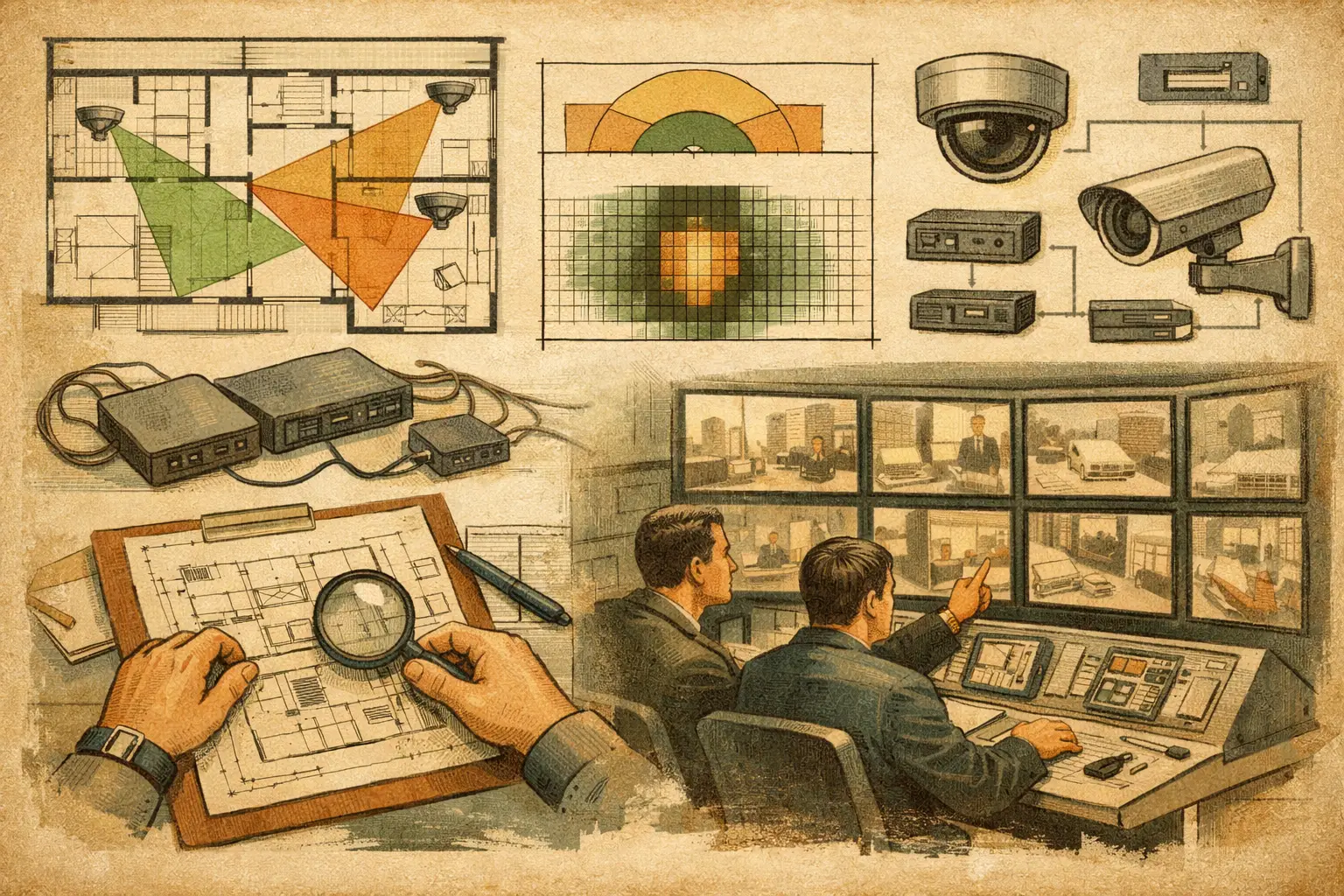
A camera symbol placed on a floor plan is not evidence of usable surveillance coverage. It may look correct in a presentation, yet miss the face at an entrance, lose a corridor behind a partition, or exceed the available network capacity. A browser based CCTV design review gives project teams a shared way to test these conditions before cameras are installed, using the same drawing, geometry, camera inputs, and technical outputs.
For consultants, installers, architects, and project owners, the value is not simply viewing a design in a web browser. The value is traceability. Reviewers should be able to see why a camera is located where it is, what task it is expected to support, where its field of view is obstructed, and what assumptions remain to be verified during installation.
Start With a Calibrated, Reviewable Base Drawing
A design review is only as credible as its spatial reference. Import the current floor plan, site plan, or reflected ceiling plan, then calibrate its scale against a known dimension. A drawing that is visually clear but incorrectly scaled will produce misleading distances, fields of view, and pixel-density calculations.
The reviewer should confirm the drawing revision, the units used, and the calibration reference. A dimensioned structural grid, a verified room length, or a measured external boundary can provide a practical scale reference. If the drawing is preliminary, record that limitation rather than treating calculated results as construction-ready facts.
Next, review the physical geometry. Walls, doors, glazing, columns, counters, racking, turnstiles, and major equipment can materially affect coverage. In many early-stage layouts, camera cones are drawn over walls as if the building were transparent. That may be acceptable for a high-level budget discussion, but it is not sufficient for an engineering review.
A useful browser-based workspace keeps the plan, geometry, cameras, and review comments together. This reduces the common problem of updating a CAD export while an old spreadsheet and a separate marked-up PDF continue circulating among the project team.
Define the Surveillance Task Before Reviewing Placement
The question is not simply whether an area is visible. The question is what the camera must allow a user to do in that area. A loading dock overview, an employee entrance, a cash-handling point, and a vehicle gate may each require different levels of scene detail.
This is where pixel density and DORI become practical review tools. Pixel density, commonly expressed as pixels per meter or PPM, relates the available image detail to the width of the scene. DORI provides a structured way to discuss detection, observation, recognition, and identification tasks. It helps replace vague language such as “cover the lobby” with a defined operational requirement at a specific location.
During review, assign the required task to the target area, then check whether the selected camera configuration supports it at the relevant distance. Resolution alone is not enough. Sensor size, focal length, mounting height, tilt, direction, and scene width all influence the calculated result.
For example, increasing focal length can improve pixel density at a distant doorway, but it also narrows the field of view and may create gaps beside the target. A wider lens may show more of a parking area while providing insufficient detail at the pedestrian entrance. Neither choice is automatically correct. The right configuration depends on the task, the scene geometry, lighting conditions, and the verified camera model selected later in procurement.
Run the Browser-Based CCTV Design Review in Stages
A disciplined review benefits from a repeatable sequence. Begin by checking the drawing and calibration, then validate physical obstructions, camera assumptions, coverage results, and coordination outputs. This order matters because changes to walls or scale can invalidate later conclusions.
Review camera inputs, not only camera icons
For each camera, review the technical inputs that produce the coverage calculation: mounting height, direction, tilt, sensor size, resolution, focal length or varifocal setting, and required pixel density. Confirm whether the camera is fixed, adjustable, indoor, outdoor, or intended for a specialized position.
Mounting height deserves particular attention. A high ceiling may provide broad situational awareness but can reduce useful subject detail at ground level. A lower mount may improve facial detail but introduce vandalism risk, glare, or unwanted obstruction. Camera tilt also changes where image detail is concentrated. A steep downward tilt can be appropriate for an overview, but it may not be suitable where the operational requirement is recognition or identification at a doorway.
Reviewing these inputs in a persistent browser workspace makes assumptions visible to every discipline. The security designer can explain the intent, the architect can identify a changed partition, and the installer can flag a mounting conflict before it becomes site rework.
Check occlusion, blind spots, and overlap
A field-of-view cone should be interpreted in relation to real geometry. Review where walls terminate visibility, where open doors change the scene, and where counters, shelving, or columns conceal important activity. For exterior areas, consider gates, landscaping, parked vehicles, canopies, and future site features that may affect the view.
Blind spots are not always defects. Some may be outside the security scope, while others may be accepted because a second camera or a patrol procedure addresses the risk. The review record should distinguish between an intentional exclusion and an unresolved gap.
Coverage overlap also requires judgment. Overlap can support continuity of observation, provide alternate viewing angles, or reduce the effect of a single camera failure. Excessive overlap, however, can indicate unnecessary equipment or a design that has not been optimized around the actual surveillance tasks. Review the overlap at key transitions such as lobby-to-corridor routes, entry points, stair landings, loading areas, and perimeter gates.
Coordinate network topology early
Camera placement affects more than coverage. Each device needs a feasible path to power, communications infrastructure, recording capacity, and network equipment. A technically sound visual design can still be difficult to build if cable routes, telecom rooms, switch capacity, or wireless links have not been considered.
During the review, identify the intended network topology and group cameras by likely switch, cabinet, floor, or zone. This helps teams expose long cable runs, isolated outbuildings, constrained risers, and locations that may need separate power or network planning. Exact bandwidth, storage, and power calculations depend on verified camera settings, codec choices, frame rates, retention requirements, and network architecture. They should be confirmed as part of detailed engineering, not inferred from a camera symbol alone.
Produce a Deliverable That Can Be Challenged
A good design review produces a record that others can inspect and question. The deliverable should communicate the calibrated drawing, camera schedule, field-of-view views, coverage or pixel-density analysis, known occlusions, and outstanding assumptions. It should also identify design revision information and the person or team responsible for resolving comments.
This is particularly useful where multiple parties are involved. A project owner may need to understand coverage intent without interpreting lens calculations. An ICT team may need camera counts and topology context. An installer may need mounting locations and directions. A security consultant may need to verify that the final design still reflects the stated operational requirements after architectural changes.
CCTV Design Tool Online supports this workflow by bringing floor-plan calibration, physical geometry, camera configuration, DORI and pixel-density review, network planning, and structured reporting into one browser-based design environment. Its calculations are based on technical camera parameters rather than a single manufacturer catalog, which can be useful while specifications are still being evaluated.
Calculated views remain design guidance, not a substitute for qualified site verification. Actual performance can be affected by lighting, reflections, compression settings, installation tolerances, camera firmware, scene activity, and the final manufacturer-specific equipment. Project requirements, applicable regulations, privacy obligations, and authority expectations must be reviewed by the relevant qualified professionals.
Make Review Comments Actionable
The most productive reviews do not end with “add cameras” or “coverage looks acceptable.” They assign a location, a reason, an owner, and a next action. For example: verify final reception-desk height because it may obscure the lobby camera; revise the focal length at the staff entrance to meet the stated recognition objective; coordinate the exterior pole camera with electrical and network routes.
That level of precision prevents comments from becoming subjective markups that disappear in the next drawing issue. It also allows teams to separate genuine security risks from items that are awaiting architectural, electrical, or procurement confirmation.
The practical goal is not to create an impressive camera map. It is to create a design record that remains understandable when the plan changes, the installation team mobilizes, and a reviewer asks the most useful question on the project: what is this camera expected to achieve, and what evidence supports that decision?