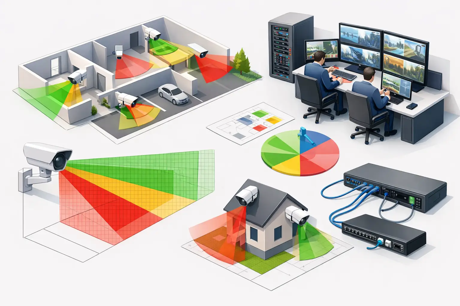
A camera mounted in the apparent center of a room can still fail the operational requirement. It may show movement without providing enough pixel density for identification, face directly into changing light, or lose critical areas behind racking, partitions, doors, and other occlusions. Effective camera placement is therefore an engineering decision, not a drawing exercise. It connects the required security outcome to physical geometry, optics, image quality, network design, and a documented basis for review.
Start Camera Placement With the Required Outcome
Before selecting a mounting point, define what the camera must achieve at each protected location. A general overview of a lobby, a person-level observation of a reception desk, and identification at an access-controlled door are different requirements. They should not be designed with the same field of view or accepted on the basis that the area is visible.
DORI provides a useful structure for this discussion: detection, observation, recognition, and identification. The required DORI level should be assigned to a specific target area, not assumed across an entire image. Pixel density, commonly expressed as pixels per meter (PPM), is then used to assess whether the selected resolution, sensor size, focal length, and distance can support that requirement in the calculated scene.
This distinction prevents a common design failure: placing a wide-angle camera to cover a large space, then expecting it to identify a person at the far edge of the frame. Wide coverage and detailed target capture are often competing objectives. A design may need an overview camera plus a dedicated identification camera rather than one device expected to perform both roles.
Build the Geometry Before Positioning Cameras
Camera views are only as credible as the underlying drawing. Import the floor plan, establish scale calibration using a verified dimension, and review the physical geometry before placing devices. A small calibration error can materially change calculated distances, coverage widths, mounting locations, and PPM results.
Walls, glazing, columns, doors, storage, racking, counters, turnstiles, and major equipment should be represented where they affect the line of sight. A simple cone drawn across a floor plan is not enough if it passes through a wall or ignores a full-height partition. The design should distinguish between an open doorway, a glazed partition, and a solid barrier because each creates different visibility and installation considerations.
Mounting height also belongs in the geometry model. A camera at 8 feet and a camera at 16 feet can cover a similar floor area, yet deliver very different facial angles, occlusion behavior, and target detail. Higher mounting can reduce tampering risk and extend the visible footprint, but it can make faces harder to capture at useful angles. Lower mounting may improve target detail while increasing vulnerability and creating more obstructions from people, furnishings, or vehicle movements.
Select the View, Then Test the Optics
Once the target zone and mounting constraints are clear, set the camera direction, mounting height, tilt, sensor size, resolution, and focal length. These inputs determine the field of view and the distribution of pixels across the scene.
A shorter focal length creates a wider field of view. It is useful for situational awareness in open spaces, corridors with close-range activity, or areas where broad movement tracking matters. The trade-off is lower pixel density at distance. A longer focal length narrows the view and concentrates pixels on a smaller target area, which can support higher DORI requirements but leaves more area outside the frame.
Tilt is equally significant. Excessive downward tilt can reduce distant coverage, distort the useful scene, and place too much image area on the floor. Too little tilt can include unnecessary ceiling or horizon while failing to show activity close to the mounting point. The appropriate angle depends on mounting height, target distance, scene depth, and whether the camera is serving people, vehicles, perimeter activity, or an access point.
At this stage, assess calculated pixel density at the actual target plane. For example, a doorway should be evaluated at the expected face location, not at the center of a wide field-of-view cone. Similarly, a vehicle entrance should be assessed at the lane and capture distance that matter to the operational requirement.
Treat Occlusion and Blind Spots as Design Inputs
Every real site contains obstructions. In office environments, these may include partitions, meeting-room doors, decorative features, and reception furniture. In warehouses, pallet racking and stored goods can alter sightlines after installation. In external areas, landscaping, gates, parked vehicles, and changing shadows may affect practical performance.
A camera placement review should identify both static and foreseeable dynamic occlusions. Static occlusions can be modeled from the drawing and site information. Dynamic occlusions require judgment: a loading bay may be clear during a survey but routinely filled with trailers; a retail aisle may be clear before merchandising is installed. These conditions do not make design analysis unnecessary. They make assumptions and limitations worth documenting.
Blind spots are not always defects. A blind spot may be acceptable where no security objective exists, where coverage would create an unsuitable viewing angle, or where a different control addresses the risk. The issue is whether the blind spot is known, assessed, and communicated. Unrecognized blind spots are the problem.
Use Coverage Overlap With Purpose
Coverage overlap can improve continuity when a subject moves between camera views, provide a secondary perspective at a critical location, and reduce the impact of a temporary obstruction. But overlap is not automatically beneficial. Excessive overlap can consume camera budget, switch ports, recording capacity, and review time while leaving other areas underserved.
Apply overlap where the operational value is clear. Entrances, corridors, junctions, cash-handling areas, loading points, and escape routes may benefit from two coordinated views. One camera can provide the context of movement while another is positioned for the required DORI level. In a long corridor, overlapping views may also avoid a single device becoming the only source of evidence for activity at a key threshold.
Review overlaps in relation to direction of travel. A camera positioned behind a person may provide clothing and movement information but not a useful frontal face view. At access points, it is often preferable to position the identification view so expected travel naturally presents the subject to the camera, while considering door swing, backlighting, and the practical location of readers or barriers.
Coordinate Placement With Installation and Network Reality
A technically sound view still requires a buildable installation. Confirm that each proposed location has a viable mounting surface, cable pathway, power approach where applicable, access for maintenance, and protection appropriate to the environment. Exterior installations introduce additional considerations such as weather exposure, vibration, lighting variation, and the physical positioning of poles or building fixtures.
Camera placement should also inform network topology. Grouping cameras by floor, zone, or communications room can simplify cable-route planning and switch allocation. Estimate bandwidth and storage using the selected camera parameters and recording assumptions, but treat these as design values rather than guaranteed live performance. Actual bitrate can vary with scene activity, compression settings, lighting, firmware behavior, and manufacturer-specific configuration.
Coordinate early with architecture, electrical, ICT, and operations teams. A camera placed after ceilings, signage, lighting, or containment are finalized is more likely to become a compromise. Conversely, security drawings should be updated when those disciplines alter the physical environment.
Validate the Design in a Repeatable Workspace
A disciplined review process turns camera positions into a traceable design deliverable. For each device, record the identifier, location, mounting height, direction, tilt, camera specification, focal length, target area, and intended DORI objective. Show field-of-view boundaries on calibrated plans, along with coverage gaps, occlusions, and meaningful overlap.
A browser-based workspace such as CCTV Design Tool Online can bring these elements together: calibrated drawings, walls and physical geometry, camera views, optical parameters, DORI and PPM calculations, blind-spot review, network planning, and structured reports. This is particularly useful when designs change repeatedly or must be reviewed by multiple disciplines. The calculated output supports engineering coordination, but it should be verified against the actual site and final manufacturer datasheets before installation.
Field validation remains essential. Construction changes, final mounting constraints, lighting conditions, lens tolerances, and scene activity can affect real-world performance. Where the security objective is critical, test representative views after installation and adjust direction, focal length, exposure settings, or supplementary coverage as needed.
The strongest camera plan is not the one with the most symbols on a drawing. It is the one where every camera has a stated purpose, every critical target has a defensible calculated view, and every meaningful limitation is visible before the installer reaches the site.