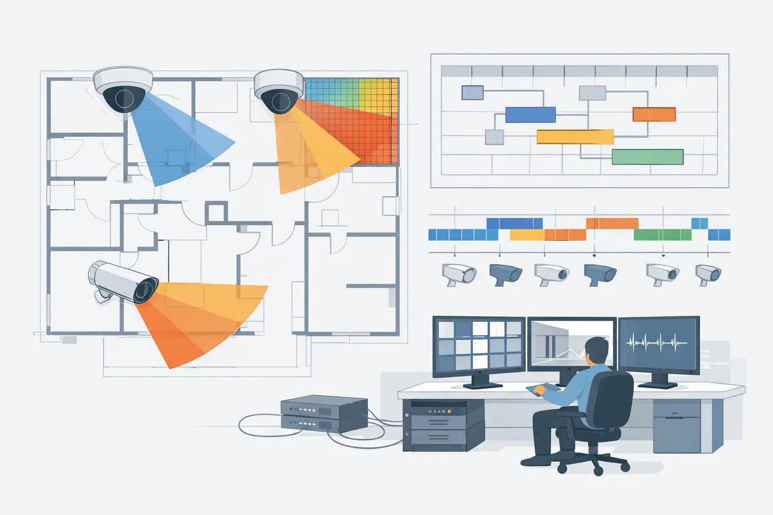
A CCTV camera schedule is where a security design becomes buildable. A coverage drawing may show camera icons and fields of view, but the schedule tells the installer, network engineer, procurement team, and reviewer exactly what each camera is intended to do. When it is incomplete or disconnected from the drawing, small assumptions about lens selection, mounting height, or network allocation can become expensive site questions.
For professional projects, the schedule should not be treated as a procurement list prepared at the end of design. It is a controlled technical register that develops alongside the floor plan, camera layout, field-of-view analysis, and network topology. Each camera entry should be traceable to a physical position, a defined surveillance objective, and measurable coverage criteria.
What a CCTV Camera Schedule Should Control
A camera schedule assigns a unique identity to every device and records the design inputs needed to specify, install, test, and maintain it. At minimum, it should connect the camera reference on the drawing to its location, camera type, optical configuration, mounting information, coverage purpose, and network details.
Its value is coordination. A security consultant may use the schedule to confirm that each observation point has the required DORI objective. An installer uses it to understand mounting and orientation. An ICT team uses it to estimate switch ports, PoE demand, VLAN allocation, and uplink capacity. A project owner can review the intended function of each camera without interpreting every coverage cone on a plan.
The schedule should describe design intent, not make unsupported promises about real-world performance. Calculated pixel density and DORI results depend on the geometry and technical inputs used in the design. Actual image quality also depends on installed height, final lens adjustment, scene lighting, motion, compression settings, environmental conditions, and the camera selected.
Start With a Stable Camera Identification System
Every camera needs a unique identifier that remains consistent across plans, reports, cable labels, recorder configuration, and commissioning records. Changing names late in the project creates avoidable traceability problems, especially where security, electrical, and ICT packages are coordinated separately.
A practical format can reflect building, floor, area, and sequence, such as CAM-L02-REC-014. The precise naming convention matters less than consistency. Define the convention before placing dozens or hundreds of devices, and reserve a method for additions without renumbering the entire system.
The schedule reference should match the label shown on the calibrated drawing. If a plan says CAM-023 while the schedule says C-23, reviewers cannot reliably confirm which field of view, cable route, or switch port applies to the device.
Define the location in operational terms
A room name alone is often insufficient. “Lobby” may contain several entrances, elevators, reception desks, and circulation routes. Add a concise position description such as “main lobby, facing north entrance doors” or “loading dock, covering bay 3 approach.” This helps the installation team validate placement when site conditions differ from early drawings.
Where a project has multiple buildings or repeated floor layouts, include the building or zone reference as a separate schedule field. This reduces ambiguity during installation and future maintenance.
Record the Camera Specification and Optical Inputs
A schedule should state the camera class required by the design, such as fixed bullet, fixed dome, PTZ, multi-sensor, or panoramic camera. It should then identify the relevant technical parameters rather than relying solely on a generic product description.
For fixed cameras, include resolution, sensor size where known, focal length or approved varifocal range, and the intended selected focal length. A 2.8-12 mm varifocal model is not a complete optical instruction if the design calculation assumes 7.6 mm. The installer needs to know the target setting and verify the resulting field of view on site.
Mounting height, direction, and tilt are equally important. A camera can meet the desired pixel density on paper but underperform if mounted lower than planned, tilted too steeply, or redirected to avoid a ceiling service. Record azimuth or viewing direction where the design process supports it, along with the height above finished floor level or above ground level.
For cameras with infrared illumination, low-light capability, analytics, or special environmental requirements, include only the project requirement or verified specification. Do not infer nighttime identification performance from resolution alone. Scene illumination, reflectance, lens aperture, shutter behavior, and the manufacturer’s documented capabilities all affect usable results.
Tie Every Camera to a Coverage Objective
The most useful schedule entries explain why the camera exists. “General surveillance” may be sufficient for broad situational awareness, but it is not sufficient where the design requires recognition, identification, or reading a detail at a defined location.
Use the project’s chosen DORI objective or pixel-density target and identify the relevant target area. For example, an entry might state: “Recognition at employee entrance threshold” or “Observation of west parking circulation lane.” If the project uses pixels per meter or PPM as a design measure, record the calculated target value and the measured distance or zone it applies to.
This distinction prevents a common design error: treating the full camera cone as equally useful coverage. Pixel density changes with distance in most fixed-camera views. A camera may provide strong detail close to the mounting point and only general observation at the far edge. The schedule should make the intended assessment point explicit.
Document occlusion and overlap decisions
Walls, doors, racking, columns, soffits, landscaping, vehicles, and open shutters can obstruct a nominal field of view. Where known occlusions affect the design, capture the constraint in a notes field and show it on the drawing. A camera aimed through an opening should not be represented as covering the wall beside it.
Coverage overlap also deserves a design note when it serves a purpose. Overlap at an entrance can support continuity if one view is temporarily blocked, while excessive overlap may add cost without improving the required outcome. The schedule does not replace the coverage plan, but it should record material decisions that a reviewer or installer must understand.
Add Infrastructure Fields Before the Design Is Issued
A camera schedule prepared only for security teams often leaves ICT coordination too late. Add fields for network switch or cabinet reference, switch port where allocated, PoE class or estimated power requirement, VLAN or network segment reference, cable identifier, and recording destination where the project scope requires them.
At early design stage, some values may remain provisional. Mark them clearly as design assumptions rather than presenting them as final installation data. This is particularly useful where final switch models, cable pathways, or recorder architecture have not been selected.
Bandwidth and storage figures should also be treated carefully. They depend on codec, frame rate, resolution, scene activity, bitrate control, retention settings, and recording policy. A schedule can reference the relevant stream profile or estimate, but it should not imply a fixed outcome until the system configuration is confirmed.
Use a Reviewable Schedule Structure
A practical CCTV camera schedule commonly includes the following fields:
- Camera ID, building, level, zone, and location description
- Camera type, resolution, sensor size, focal length, and selected lens setting
- Mounting height, mounting method, direction, and tilt
- Coverage purpose, target area, DORI objective, and calculated PPM or pixel-density result
- Drawing reference, coverage view reference, and notes on blind spots or occlusion
- Network cabinet, switch, port, cable ID, PoE requirement, and stream profile reference
- Status, revision, and verification notes
Not every project needs every field. A small office retrofit may not need a formal switch-port allocation during concept design. A campus or critical-infrastructure project may require additional asset, network, and maintenance references. The correct level of detail depends on design stage, contractual scope, and the people who must act on the document.
Keep the Schedule and Drawing in the Same Revision Cycle
The schedule fails when it is copied into a spreadsheet and forgotten while the drawing changes. A revised wall layout can alter occlusion. A changed mounting point can alter focal length, pixel density, cable length, and switch allocation. A new access-controlled door may create a coverage requirement that was not present in the original brief.
Use a controlled revision process. When a camera moves, review its field of view, DORI or PPM calculation, mounting data, and infrastructure references before issuing the next package. Include revision dates and a clear status, such as concept, coordinated design, issued for construction, or as-built, according to the project’s document-control process.
A persistent design workspace can reduce the gap between visual planning and documentation. In CCTV Design Tool Online, camera placement, calibrated scale, physical geometry, field-of-view calculations, and structured reporting can be reviewed within the same design workflow. The resulting documentation still requires qualified project review, particularly when site conditions or jurisdiction-specific requirements affect the final installation.
Review the Schedule From Each Project Role
Before issue, a security designer should check that every camera has a defined purpose and that the stated optical inputs match the coverage calculation. The installer should be able to locate and mount each device without guessing. The network team should be able to understand device counts, power assumptions, and connection points. The client or reviewer should be able to trace each schedule line back to a camera symbol and coverage area.
If any one of those people has to make an assumption, the schedule needs another pass. The goal is not to create a longer document. It is to remove ambiguity at the points where design intent becomes physical work.
A well-maintained camera schedule gives every camera a reason, a location, and a measurable role. That discipline makes design reviews clearer now and makes changes, commissioning, and future expansion far easier to manage.