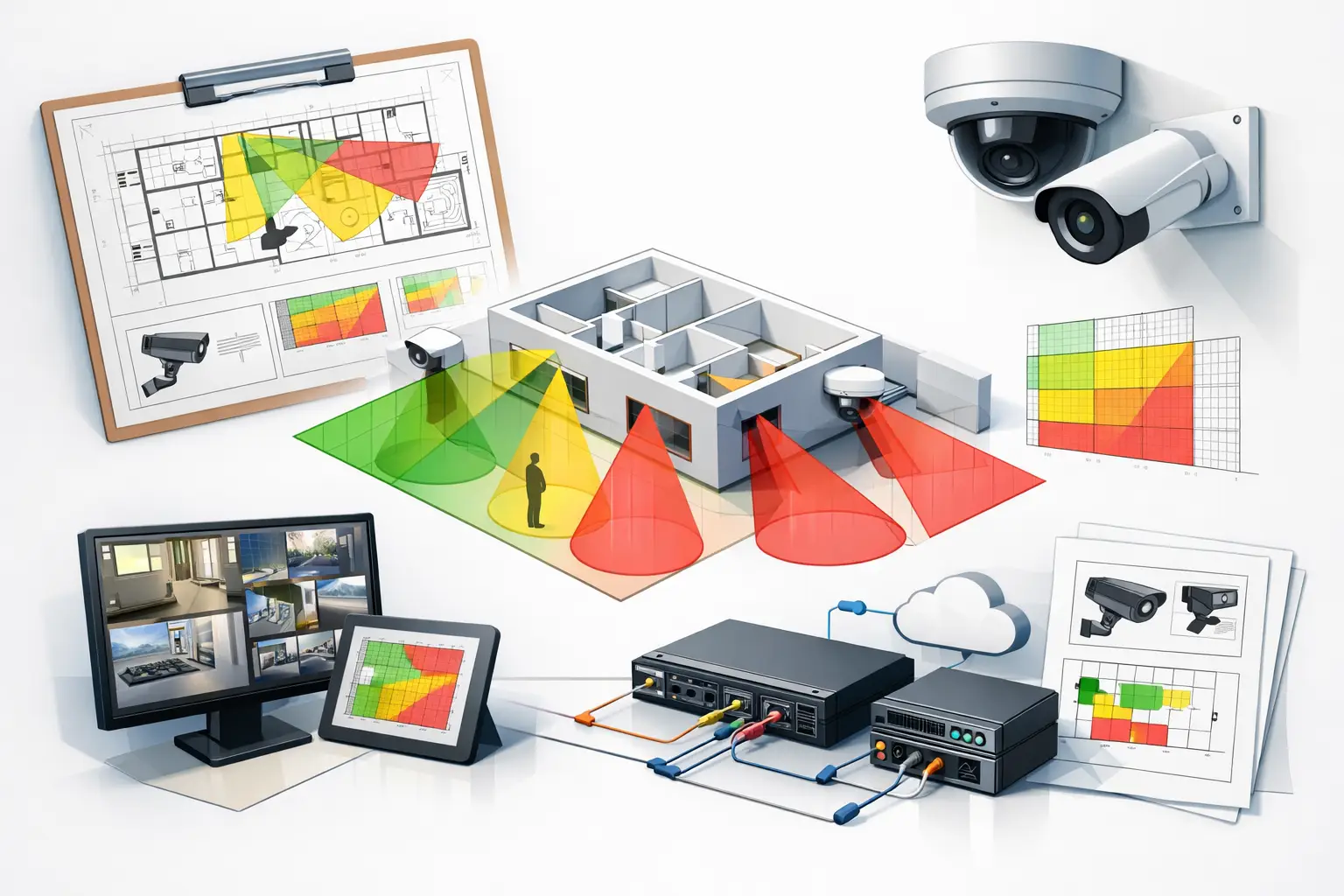
A surveillance drawing can look complete and still fail the first serious review. A camera icon placed over a lobby, parking area, or corridor does not prove that the required subject is visible at the required quality. Professional CCTV design converts an architectural drawing into a set of measurable, reviewable decisions: what each camera must achieve, where it can be mounted, what obstructs it, how it connects, and how the finished system will be documented.
That distinction matters whenever a project involves more than a simple perimeter camera. Installers need placement information they can build from. Consultants need assumptions they can defend. Architects need to understand how devices affect the space. Project owners need a clear explanation of what their investment will actually cover. The design process must give every one of those parties a consistent answer.
A CCTV design starts with a calibrated drawing
The floor plan is the reference model for every decision that follows. Import the available PDF, PNG, JPG, or DXF drawing, then calibrate it against a known dimension. A drawing that is only slightly out of scale can create misleading distance measurements, pixel-density results, storage estimates, and cable runs.
Calibration should be treated as an explicit project assumption, not a background task. Identify a dimension that is reliable, such as a structural grid, a labeled corridor length, or a surveyed exterior boundary. If the source plan is conceptual or has been resized during export, record that limitation before relying on calculated distances.
Next, establish the geometry that affects visibility. Walls, rooms, doors, glazing, gates, and other openings are not merely drafting details. They define where a camera can see and where its view is blocked. An idealized camera cone that passes through walls may look reassuring, but it is not a valid coverage model.
Reviewable AI-assisted geometry can reduce the time required to prepare a complex plan, but it should not remove professional judgment. Confirm wall boundaries, correct openings, and inspect areas where architectural symbols or low-resolution scans may have been interpreted incorrectly. The output should be a trusted spatial model, not just a cleaned-up image.
Define the operational objective before placing cameras
Camera count is not a security objective. Before choosing lenses or mounting positions, define what must be achieved at each area. A reception desk may require identification of visitors. A warehouse aisle may require observation of activity and detection of unauthorized entry. A loading dock may require vehicle context, license plate capture under specific conditions, and usable evidence at night.
DORI provides a practical framework for stating that objective. Detection, observation, recognition, and identification represent progressively higher requirements for subject detail. The required level depends on the scenario, the operational response, and the consequences of an unclear image.
For example, a wide-angle camera may detect movement across a parking lot while being unsuitable for identifying a person at the far edge. That is not necessarily a design failure. It becomes a failure when the coverage drawing or proposal implies an identification capability the camera cannot deliver.
Document the target requirement by zone. A compact coverage schedule can connect each area to its purpose, priority, required DORI level, lighting assumption, and associated camera or cameras. This prevents a familiar problem: a system that has broad visual coverage but no verified evidence-quality coverage where the risk is highest.
Model field of view as an engineered result
Once objectives are clear, configure each camera using real design inputs. These include sensor format, resolution, lens or focal length, mounting height, direction, tilt, and installation location. The resulting field of view should be represented on the calibrated plan and evaluated against the actual geometry.
A camera mounted high in a lobby can see a large area, but the steep viewing angle may reduce facial detail. A lower camera may improve subject detail but introduce tampering risk or be blocked by furniture, signage, and pedestrian traffic. A varifocal lens can provide flexibility during commissioning, but it does not replace a documented intended view.
Occlusion review is essential. Walls should block the camera model, and openings should permit visibility only where the building geometry allows it. Consider fixed obstructions as well: shelving, racks, trees, canopies, parked vehicles, display fixtures, and access-control portals can materially change the usable image.
The best placement is often a trade-off between coverage width, detail at the target distance, mounting practicality, lighting direction, and cable route. There is no universal camera height or lens setting that solves every space. A disciplined design makes the compromise visible before installation rather than leaving it to field adjustment.
Review blind spots and overlap deliberately
Blind spots are not always unacceptable. Some may be low-risk areas, inaccessible voids, or spaces outside the defined scope. The key is that they are identified and accepted rather than discovered after an incident.
Overlap also deserves a purpose. In a high-value entrance, overlapping views can provide continuity if one camera is obstructed, improve event reconstruction, and capture different angles of a subject. In a low-risk corridor, excessive overlap may consume budget without improving the operational outcome. Review coverage summaries by zone to distinguish intentional redundancy from accidental duplication.
Validate pixel density and DORI at the target location
A visual cone alone cannot confirm image usability. Pixel density and DORI analysis connect camera configuration to the level of detail available at a specific distance or target area. This is where a design moves from “the camera sees it” to “the camera is expected to support the stated task.”
Validate the critical edge of each coverage area, not only the location nearest the camera. If an entrance requires identification, test the likely path of travel and the point at which a person will be captured. If a camera is intended to monitor a cash-handling area, evaluate the actual transaction position. For exterior scenes, assess the range where people, vehicles, or gates are expected to appear.
These calculations depend on assumptions. Resolution can be reduced by compression, low light, motion blur, poor focus, dirty housings, and scene dynamics. DORI analysis is a design validation method, not a guarantee that every recorded frame will be evidentiary under every condition. State the operating assumptions clearly, especially for nighttime and high-contrast scenes.
Connect coverage decisions to network and installation planning
A camera plan becomes more useful when it remains connected to the technical details needed to deploy it. Each camera should have a persistent identity and associated configuration, rather than being a disconnected symbol on a page. That identity can carry location, device type, lens setting, IP information, power method, recording assumptions, and notes for installation.
Network planning should account for bandwidth, switch capacity, uplink demand, PoE budgets, and the practical location of communications cabinets. A design that meets coverage requirements but exceeds available PoE capacity or forces an impractical cable route will create avoidable site changes.
Simulation and scenario review can be valuable before equipment is ordered. Test whether directional cameras cover expected approaches, whether an entrance remains effective when doors are open, and whether a loading area has usable viewing angles during normal operations. The closer the plan reflects real site conditions, the fewer assumptions are deferred to commissioning.
Generate a deliverable that supports approval and installation
The final report should not be an afterthought assembled from screenshots, spreadsheets, and handwritten markups. It is the project record that allows others to review the design, quote it accurately, install it consistently, and approve it with confidence.
A structured deliverable typically includes the calibrated plan, camera schedule, field-of-view diagrams, DORI or pixel-density results, coverage summaries, blind-spot notes, network assumptions, and a clear list of exclusions. It should show what was designed, why it was selected, and what conditions must remain true for the design to perform as intended.
This connected approach is the purpose of platforms such as CCTV Design Tool: a change to a camera, wall, or plan can remain tied to the coverage analysis and report instead of forcing teams to reconcile multiple disconnected files. Revision control is especially valuable when architectural changes, owner feedback, or authority requirements arrive late in the project.
For project owners and approval teams, clarity is as important as technical depth. Use diagrams that make coverage and limitations understandable without removing the underlying engineering evidence. A reviewer should be able to see the operational intent quickly, then trace it back to camera settings, geometry, and documented assumptions when needed.
A well-prepared CCTV design does more than specify equipment. It gives the project team a defensible basis for decisions before ladders are deployed, cable is pulled, and installation changes become expensive.