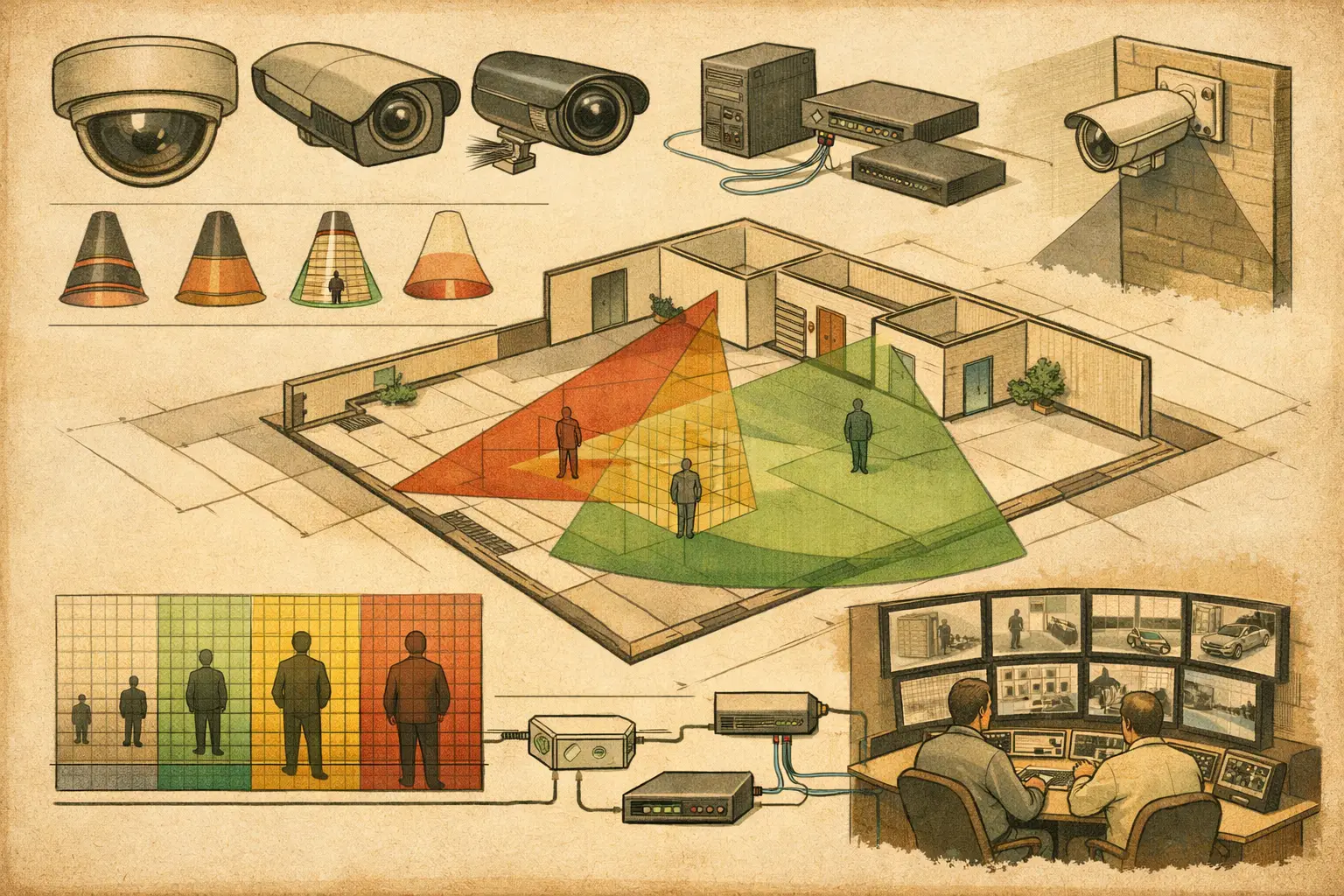
A camera can be correctly located on a drawing and still fail its operational purpose because the lens is wrong. CCTV lens selection determines how much of the scene enters the image, how large a subject appears at the target distance, and whether the available pixels support detection, observation, recognition, or identification.
For installers and designers, the common mistake is starting with a familiar focal length. A more reliable process starts with the operational task, the target location, and the physical limits of the scene. The lens then becomes a calculated design choice rather than a default item on a camera schedule.
Start With the Required Detail, Not the Camera Position
Before selecting a focal length, define what the camera must achieve at each relevant distance. A wide overview of a lobby may support situational awareness and detection, while an entrance camera may need sufficient pixel density at a face-capture zone. A loading yard may require coverage across a broad area, but the vehicle gate or pedestrian access point can require a different level of detail.
DORI provides a useful vocabulary for this discussion: detection, observation, recognition, and identification. These are design objectives, not a promise of real-world evidential performance. Lighting, motion, compression, shutter settings, focus accuracy, subject angle, and the camera's actual imaging performance all affect the installed result.
Pixel density, often expressed as pixels per meter or PPM, connects the objective to the image geometry. The required PPM should be established from the project brief, risk assessment, client requirements, or applicable project criteria. Once that target is known, calculate whether the camera resolution and proposed field of view provide it at the required range.
This changes the design question from "Will the camera see the door?" to "At the door, will the camera deliver the required pixel density across the defined target zone?" That distinction is central to defensible design review.
How Sensor Size and Focal Length Shape the Image
A lens does not create coverage independently. Its field of view is determined by the relationship between focal length and active sensor dimensions. For a given sensor size, a shorter focal length creates a wider field of view. A longer focal length narrows the view and makes distant subjects occupy more pixels.
This is why a 2.8 mm lens may be appropriate for a compact room or a broad overview near the camera, while an 8 mm or 12 mm lens may be needed to concentrate available pixels on a gate, corridor endpoint, or perimeter target. The numbers alone are not interchangeable. A 2.8 mm lens on one sensor format can produce a materially different field of view than the same focal length on a larger or smaller sensor.
Resolution also matters, but it does not remove optical limits. Increasing resolution can improve pixel density within a fixed field of view, yet it may not solve a poorly defined target zone. A high-resolution camera aimed across an excessively wide scene can still provide inadequate detail where it is needed. Conversely, a narrow lens can produce strong target detail while losing context and creating adjacent blind spots.
For fixed lenses, the selected focal length should be documented alongside sensor size, resolution, mounting height, direction, tilt, and target distance. For varifocal lenses, document the intended focal setting used in the calculation. Stating only the lens range, such as 2.8-12 mm, does not describe the designed field of view.
Use CCTV Lens Selection as a Coverage Exercise
The most useful workflow is to model the actual environment before finalizing the lens. Import and calibrate the floor plan so distance measurements are meaningful. Then position the camera, set its mounting height, direction, tilt, sensor parameters, resolution, and lens focal length. Review the resulting field of view at the target plane, not only as a cone drawn from the camera.
Physical geometry changes the answer. Walls, columns, racking, partitions, glazing details, canopy edges, and door leaves can occlude a view that appears clear on a simple two-dimensional drawing. In outdoor designs, changes in elevation, landscaping, fences, and vehicle movements may also affect the usable image area.
A disciplined review should test four questions:
- Does the field of view include the defined target zone?
- Does pixel density meet the stated task at the required distance?
- Do walls or objects create occlusion, blind spots, or misleading overlap?
- Does the proposed view retain enough context for operators to understand activity around the target?
The answer is frequently a trade-off. Tightening the focal length can improve PPM at a doorway but may reduce the approach view needed to track a person entering the scene. Widening the lens can show the entire reception area but may reduce facial detail at the far side. In many cases, the correct response is not a compromise lens but two cameras with distinct roles: one overview camera and one task-specific camera.
Account for Mounting Height, Tilt, and Subject Angle
Lens calculations are often discussed as horizontal distance and horizontal field of view. Real installations are three-dimensional. A camera mounted high above an entrance and tilted sharply downward may cover the floor area effectively while capturing a poor subject angle for a face-based identification objective.
Mounting height also changes the relationship between near and far coverage. With a wide lens at a high mounting point, the foreground may occupy a substantial part of the image while distant targets receive relatively few pixels. Strong perspective can make the camera cone look comprehensive even when target detail varies significantly across the scene.
Review the target plane that matters. For pedestrian monitoring, this may be a vertical zone around the expected subject position. For a vehicle lane, it may be a defined roadway area and approach direction. For goods handling, it may be a loading bay, dock door, or restricted access line. The design output should show where the pixel-density calculation applies and where it declines.
Lighting must be reviewed separately from lens geometry. Backlight at glazed entrances, infrared reflections from nearby surfaces, glare from headlights, and low-light noise can reduce usable detail even where a calculated PPM result appears suitable. The lens choice may remain correct, but camera settings, illumination, placement, or scene treatment may need further engineering review.
Fixed, Varifocal, and Motorized Lenses
A fixed-lens camera is often suitable when the mounting position, target distance, and field of view are stable and clearly defined. It simplifies specification and can reduce the risk of an installer setting a varifocal lens too wide during commissioning. Its limitation is obvious: changes in the room layout or mounting position may require a different camera or lens.
A varifocal lens offers flexibility during commissioning, particularly where final site dimensions differ slightly from design drawings. That flexibility should not replace a specified setting. The camera schedule should identify the planned focal range and the intended field of view so the installed view can be checked against the design.
Motorized varifocal lenses can support remote adjustment and practical maintenance, but the same engineering principles apply. A motorized lens is not automatically the best option for every camera. Consider the operational target, access constraints, project maintenance strategy, and verified manufacturer specifications.
Review Overlap Without Duplicating Coverage
Coverage overlap is valuable when it has a purpose. At an entrance, one camera may provide a wide contextual view while another is configured for higher detail at the threshold. Along a perimeter, overlap can reduce gaps between adjacent scenes and provide another viewpoint when a vehicle or structure causes temporary occlusion.
Unplanned overlap, however, can consume camera count, storage, bandwidth, switch ports, and installation time without improving the operational outcome. Lens selection should therefore be coordinated with network topology and recording requirements. Narrower fields of view may lead to additional cameras for complete area coverage; wider fields may reduce camera count but raise the risk of insufficient target detail. Neither approach is inherently better.
A design workspace such as CCTV Design Tool Online can make these decisions traceable by combining calibrated drawings, physical geometry, camera settings, field-of-view visualization, DORI and PPM review, and report-ready outputs. The calculation remains a design input that should be verified against site conditions and final commissioning images.
Document the Lens Decision for Handover
The final deliverable should let another professional understand why each lens was selected. For every camera, record the camera location, mounting height, direction, tilt, sensor size, resolution, lens type, focal length or focal setting, target zone, and intended DORI or pixel-density objective. Where a view is constrained by an obstruction or architectural change, record that condition rather than hiding it behind a generic coverage cone.
This level of documentation helps security, ICT, architectural, and installation teams coordinate before equipment arrives on site. It also makes revisions more controlled when a door moves, a ceiling height changes, or a client asks for greater detail at a particular point.
The strongest lens choice is rarely the widest or the longest available. It is the one that gives the required detail at the required location, preserves the necessary context, and remains understandable to the people who must install, test, and operate the system.