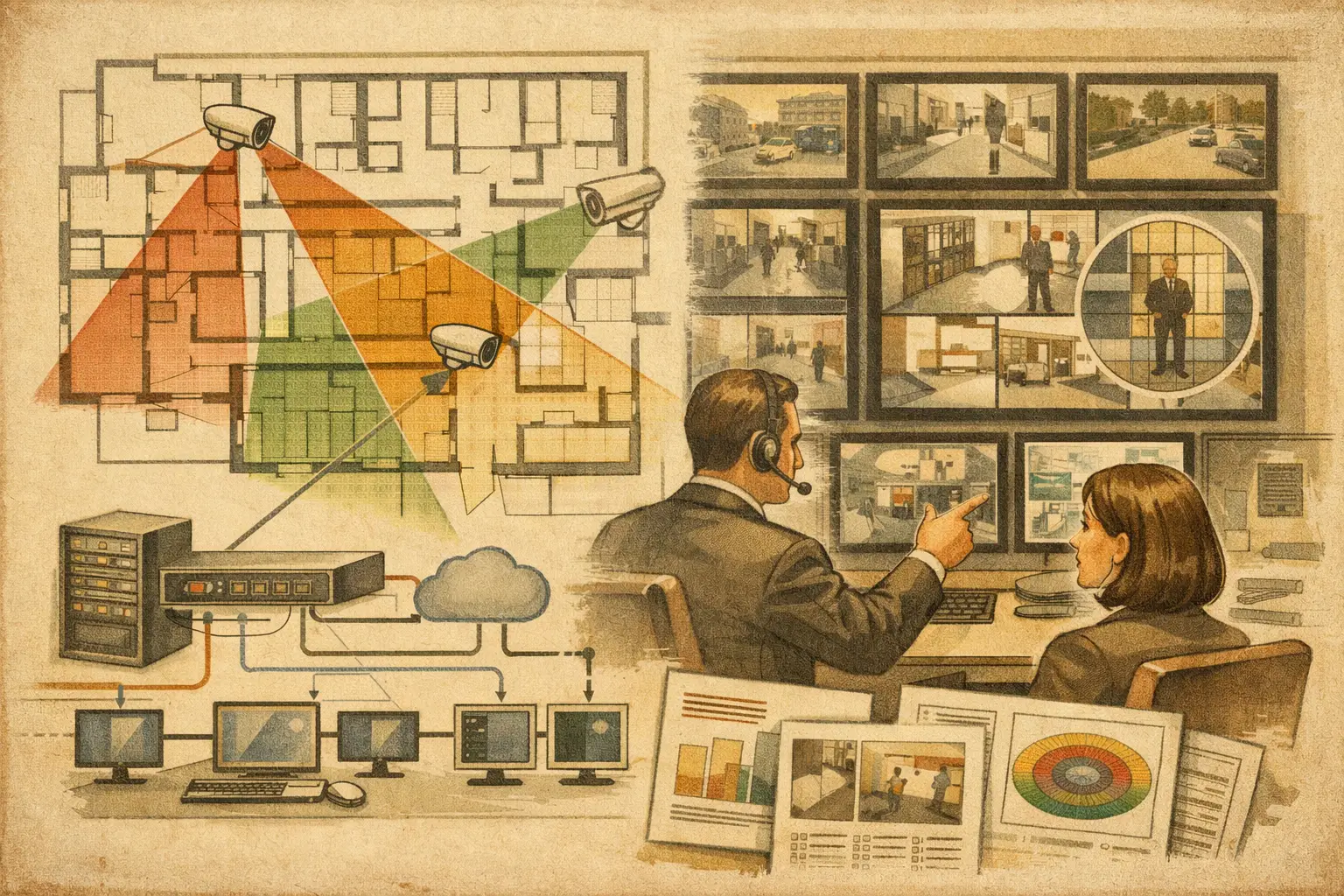
A client can approve a camera symbol on a floor plan without understanding what that camera can actually see. The problem emerges later: a reception desk blocks a view, a long corridor does not meet identification criteria, or a proposed network route is impractical. CCTV system simulation for clients closes that gap by turning an abstract layout into a traceable visual and technical design review.
This is not a sales animation or a promise of installed performance. It is an engineering representation of the proposed system based on defined inputs: calibrated scale, physical geometry, camera position, mounting height, lens settings, sensor size, resolution, direction, tilt, and coverage objective. When those inputs are visible, clients can make better decisions before equipment is ordered or installation begins.
What a CCTV system simulation should show
A useful simulation answers more than the question, “Where are the cameras?” It should show the relationship between each camera and the environment it is intended to protect.
At the most basic level, the drawing must be imported and scale-calibrated correctly. A coverage cone on an uncalibrated PDF may look convincing, but its distance calculations have little engineering value. Once the scale is established, the design team can position cameras against actual dimensions and assess the resulting field of view.
The camera model should reflect physical conditions. A wall, column, glazed partition, racking system, or doorway can create an occlusion that a simple two-dimensional cone ignores. Geometry-aware simulation helps distinguish visible floor area from theoretical coverage. This is particularly valuable in lobbies, warehouses, parking structures, campuses, and mixed-use developments where obstructions drive placement decisions.
The simulation should also communicate image usability, not just visibility. A distant person may be visible in the scene but lack sufficient pixel density for the intended task. Reviewing PPM and DORI zones makes the conversation more precise: is the camera intended to detect activity, observe behavior, recognize a known person, or identify an unknown person? Those outcomes require different image detail at different distances.
Start with the client’s operational question
Technical teams often begin by selecting cameras. A better starting point is the operational question the client needs the system to answer.
For an office entrance, the requirement may be to identify people crossing a controlled threshold. At a loading area, the priority may be observing vehicle movements and contractor activity. In a large open yard, the client may need detection coverage along a perimeter, supported by targeted cameras at gates and access points. Each scenario affects focal length, mounting height, camera direction, overlap, and required pixel density.
This discussion also exposes trade-offs early. A wide-angle lens covers more area but spreads the available pixels across a larger scene. A narrow field of view can provide stronger detail at distance but may leave adjacent areas outside coverage. Raising a camera can reduce tampering risk and broaden the scene, while also changing viewing angles and increasing the chance that shelving, canopies, or vehicles create blind spots.
Simulation gives the client a way to see these trade-offs rather than receiving a technical explanation after the layout has already been fixed.
Build the simulation from verifiable inputs
A credible client review depends on disciplined input data. If the base drawing is incomplete or the ceiling height is assumed, the simulation should state those assumptions. This is not a weakness. It gives the project team a defined list of items to verify during a survey or coordination meeting.
Calibrate the drawing and review physical geometry
Import the current floor plan, site layout, or elevation and calibrate it using a known dimension. Then review walls, openings, partitions, and major obstructions. For external areas, include fences, gates, buildings, landscape features, and other structures that influence sightlines.
The level of detail should fit the design stage. A concept design may model primary walls and likely obstructions, while a detailed construction design should reflect confirmed room layouts, ceiling conditions, and mounting surfaces. Treating a preliminary architectural plan as final can create false confidence.
Configure cameras by specification, not by logo
A brand-agnostic simulation begins with technical parameters rather than a manufacturer name. Configure resolution, sensor size, focal length, mounting height, direction, tilt, and any relevant lens range. These values define the calculated field of view and pixel-density distribution.
Manufacturer-specific performance can still matter later, especially for low-light behavior, dynamic range, analytics, and lens options. However, those characteristics should be checked against the selected product’s official documentation rather than inferred from a generic camera category. The simulation establishes the optical and spatial design basis; it does not replace product verification.
Review coverage, DORI, and blind spots together
A camera schedule alone cannot show whether two adjacent cameras leave a gap at a doorway or create excessive overlap across an unimportant area. The review should combine camera fields of view with DORI or PPM coverage layers and the modeled geometry.
Some overlap is intentional. At critical entries, cash-handling points, corridors, and vehicle gates, overlapping views can provide continuity if one camera is obstructed or looking away from an event. Too much overlap, however, can consume budget and network capacity without improving the client’s operational outcome. The question is not whether every colored area overlaps. It is whether the overlap supports the required observation task.
Present the design in a sequence clients can follow
Clients do not need to become lens specialists to approve a sound design. They do need a review process that connects technical choices to their facilities and risks.
Begin with a site or floor-plan view that identifies zones, access points, and camera locations. Then review camera views individually, showing direction, field of view, mounting height, and the areas affected by occlusion. Follow this with a DORI or pixel-density view that explains whether each key zone is being designed for detection, observation, recognition, or identification.
After coverage, bring in the infrastructure implications. A simulation should support network planning by showing likely device locations, cable pathways, cabinet or switch locations, and network topology. It does not replace a detailed ICT design, power calculation, or cybersecurity review, but it helps security, architectural, and IT stakeholders identify coordination issues while changes are still manageable.
This order matters. Starting with a camera count tends to frame the discussion around cost alone. Starting with operational zones and visible design outcomes gives the client a basis for deciding where detail, redundancy, and infrastructure investment are justified.
Use simulation to manage revisions without losing traceability
Most CCTV designs change. A tenant revises a reception layout, an architect moves a door, a client adds a gate, or an installer identifies a mounting constraint during survey. When drawings, manual calculations, spreadsheets, and reports live in separate tools, each change can produce mismatched information.
A persistent design workspace makes revisions easier to review. The adjusted wall geometry can affect the visible field of view. A revised camera location can update coverage analysis. The camera schedule and report can be regenerated from the same design basis. This does not eliminate engineering review, but it reduces the chance that a client approves one version of the plan while the installation team works from another.
CCTV Design Tool Online supports this workflow by combining calibrated drawings, modeled geometry, camera specifications, visual coverage analysis, and reporting within one browser-based workspace. For a consultant or integrator, the practical benefit is not merely a better presentation. It is a clearer chain from design input to documented output.
Keep calculated results separate from field verification
A simulation is a decision-support tool, not a site acceptance test. It can calculate expected coverage based on the design inputs, but actual field performance depends on conditions that may not be fully represented in the model.
Lighting changes, reflections, seasonal vegetation, parked vehicles, construction deviations, lens tolerances, compression settings, and final mounting positions can all affect the installed result. The client should understand which elements are calculated, which are assumptions, and which must be checked during commissioning.
The same principle applies to project requirements and regulatory expectations. A visual design review can help demonstrate intent and coordinate stakeholders, but applicable laws, privacy obligations, authority requirements, and project specifications must be confirmed by qualified professionals in the relevant jurisdiction. No coverage drawing alone establishes compliance or guarantees approval.
Make the deliverable useful after the meeting
The strongest client simulation does not disappear once the presentation ends. It becomes part of a structured deliverable that can be reviewed by project managers, architects, installers, IT teams, and security operations.
Include the calibrated plan, camera locations, camera parameters, field-of-view views, coverage or DORI analysis, assumptions, identified blind spots, recommended overlap areas, and relevant network-planning information. Use clear camera IDs so that the plan, schedule, and report refer to the same devices. If an area remains outside the intended coverage scope, mark it clearly rather than allowing it to be mistaken for an oversight.
A client does not need a promise that every risk has been removed. They need a design they can inspect, challenge, and approve with a clear understanding of what each camera is intended to achieve. That is where simulation earns its value: it turns CCTV design from a collection of symbols into an engineering conversation that can continue through coordination, installation, and verification.