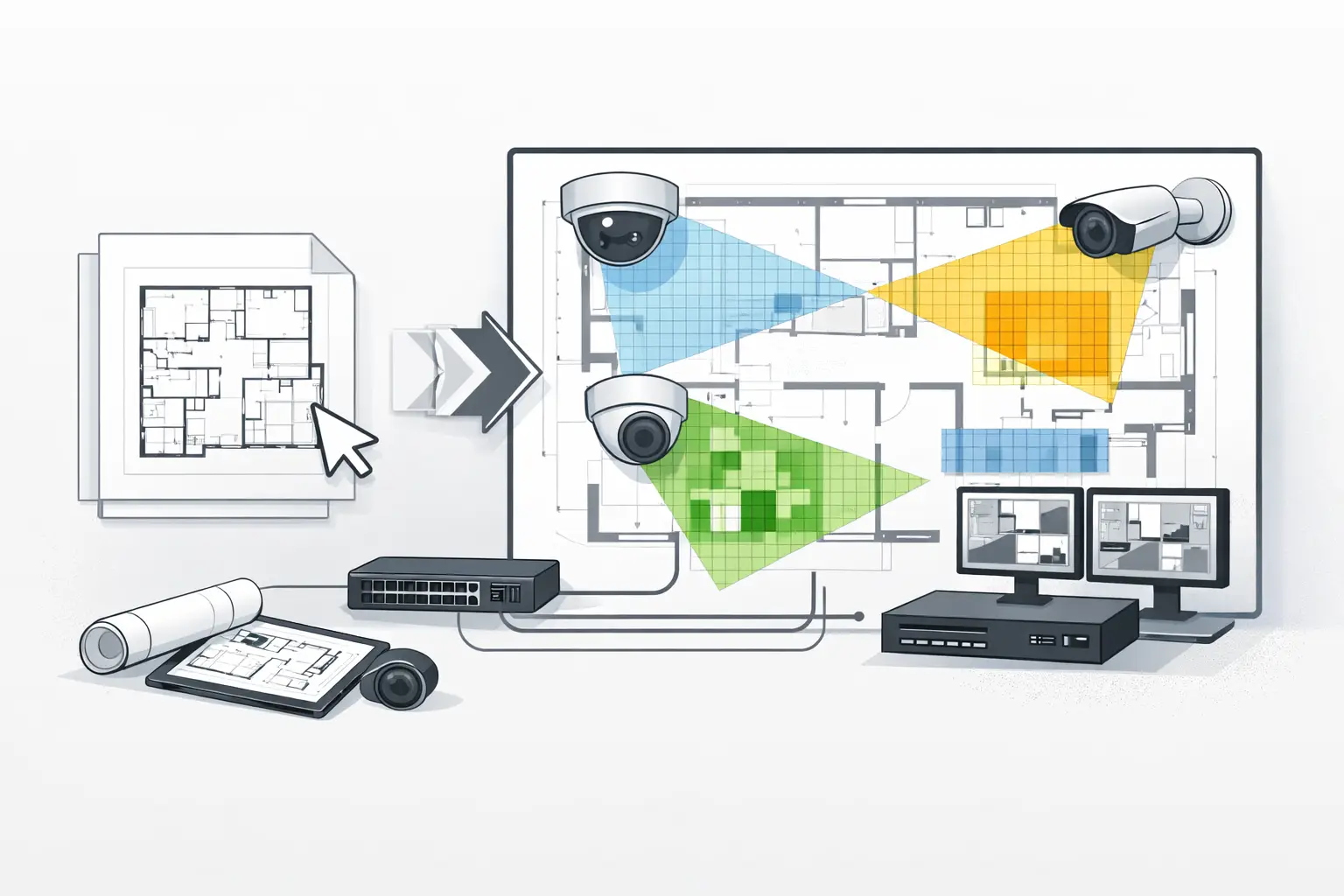
A PDF plan can look correct on screen and still produce unusable CCTV calculations if its scale, orientation, or physical geometry is wrong. Knowing how to import PDF floor plans is therefore not just an administrative step. It establishes the coordinate base for camera positions, field of view calculations, pixel density, DORI review, cable routes, and the final technical deliverable.
For security consultants, integrators, and installers, the objective is not simply to place a drawing behind camera icons. The objective is to turn a reference document into a controlled design workspace where every calculated result can be traced back to a verified physical dimension.
Start With the Right PDF Source
Request the most current issued drawing before importing anything. This should include the drawing revision, level or building identifier, drawing scale, and any available dimensions. A plan exported from an architectural or construction drawing is usually more useful than a scanned print, but both can be used if the scale reference is clear.
PDF floor plans generally fall into two categories. A vector PDF retains linework, text, and geometry from the source CAD or BIM drawing. It is usually sharper at high zoom levels and often easier to interpret. A raster PDF is effectively an image inside a PDF, commonly created from a scan or low-resolution export. Raster plans can still support a CCTV design, but wall edges, doors, and dimension text may require more careful review.
Before upload, check that the PDF page represents the area you intend to design. Multi-page packages often contain title sheets, reflected ceiling plans, fire plans, elevations, and several floor levels. Importing the wrong sheet can create avoidable coordination errors, particularly where camera mounting locations depend on ceiling layout or structural obstructions.
If the drawing is confidential, follow the project team's document-control process before uploading it to any browser-based platform. The imported plan should also retain a clear project, building, level, and revision naming convention.
How to Import PDF Floor Plans Into a CCTV Workspace
Import the PDF into the correct project and create a separate workspace or level for each floor, zone, or external area. A disciplined structure matters once the project includes multiple buildings, risers, and camera schedules. Mixing several levels into one design canvas makes it difficult to validate coverage or coordinate network topology later.
During import, confirm that the page is displayed without unintended cropping, rotation, or stretching. A plan rotated by 90 degrees is not inherently a problem, but the orientation should be intentional and consistent with the rest of the project. Where north orientation is relevant to external coverage, site coordination, or report review, retain it visibly on the drawing.
Do not assume that a PDF's printed scale, such as 1:100, is sufficient for software calculations. That scale applies only when the drawing is printed at a specific paper size. A PDF viewed in a browser can be resized, exported, or converted, so it needs scale calibration against a known real-world distance.
The import output should be a readable base plan with a confirmed level name, drawing revision, and a reliable reference dimension ready for calibration. At this stage, it is a drawing background, not yet an engineering model.
Calibrate Scale Before Placing Cameras
Scale calibration converts distances measured on the imported plan into actual site dimensions. It affects nearly every downstream calculation: camera-to-target distance, field of view width, pixel density in pixels per meter or PPM, DORI assessment, cable lengths, and coverage area.
Choose a dimension that is long, clear, and unlikely to be affected by drawing distortion. An overall building grid, a dimensioned corridor length, or a structural bay is often more reliable than a short door opening. Avoid using dimensions that are obscured by revision clouds, text, furniture, or image artifacts.
Set the calibration line by selecting two known points on the plan, then enter the actual dimension and unit. Use the project unit system consistently. If architectural dimensions are in feet and inches while security specifications use meters, establish the primary design unit before continuing and document the conversion approach where needed.
A useful calibration check is to measure at least two additional known dimensions in different parts of the drawing. If a corridor is shown as 30 feet long but the calibrated plan measures 26 feet, stop and investigate. The issue may be an incorrect selected reference, a page scaling problem, a distorted scan, or an outdated architectural drawing.
For scanned plans, calibration accuracy can vary across the sheet if the original was skewed during scanning. In that case, use the plan as a reference only after considering whether a clean digital export can be obtained. A calculated field of view based on distorted geometry should not be treated as a verified installation outcome.
Review Walls, Openings, and Physical Geometry
A floor plan does not automatically contain usable occlusion data. Camera coverage depends on physical obstruction, not just linework. Partition walls, glazed walls, doors, shelving, columns, counters, lift cores, machinery, and ceiling-mounted services can all affect what a camera can see.
Review the imported plan and create or verify the geometry that will be used in the coverage model. Walls should follow actual wall faces as closely as practical, especially in narrow corridors, reception areas, retail spaces, and rooms with access-controlled doors. A wall drawn several feet out of position can make a camera appear to see through a corner or conceal a blind spot.
Openings need similar attention. A doorway may be open during normal operation, closed outside working hours, or fitted with a glazed panel that produces reflections rather than a clear image. The appropriate design assumption depends on the operational requirement. Document significant assumptions rather than treating every opening as permanently transparent.
Mounting height is another essential input. A 2D plan shows camera location but does not establish whether a proposed view is obstructed by a bulkhead, duct, sign, rack, or ceiling feature. Use elevations, reflected ceiling plans, site photographs, and coordination drawings where available. The design model can calculate a camera's geometry from its mounting height, tilt, direction, focal length, sensor size, and resolution, but it cannot verify unmodeled site conditions.
Position Cameras Only After Geometry Is Credible
Once the plan is calibrated and physical geometry has been reviewed, place cameras according to operational objectives rather than visual symmetry. Define what each camera needs to achieve: observe activity, detect a person entering an area, recognize a known individual, or identify a person at a controlled point. These objectives should align with the project's stated requirements and any applicable client or authority criteria that have been independently verified.
For each camera, enter the technical parameters from the applicable manufacturer datasheet. Resolution alone does not determine performance. Sensor size, focal length, mounting height, tilt, target distance, scene lighting, compression, motion, and the recorder configuration all influence field results.
Review the projected field of view against walls and obstructions. In a properly modeled plan, walls should limit the visible area rather than allowing a camera cone to continue through enclosed rooms. Pay close attention to corners, corridor intersections, entrance vestibules, and areas behind doors. These are common locations for blind spots that are not obvious on an uncalibrated drawing.
Then assess pixel density at the target area, not just across the widest visible portion of the scene. DORI is useful as a design framework for discussing detection, observation, recognition, and identification tasks, but calculated PPM values are design outputs. They should be validated against the project brief, camera datasheet, scene conditions, and professional judgment before installation decisions are finalized.
Check Coverage Overlap and Network Implications
Coverage overlap can provide operational resilience at entrances, cash handling points, loading areas, and critical paths, but more overlap is not automatically better. Excessive duplication can increase camera count, bandwidth, storage, switch capacity, and installation complexity without improving the required outcome.
Use the calibrated plan to review where overlapping fields of view provide useful continuity and where they merely duplicate a broad overview. If a camera is repositioned to address an occlusion, revisit its cable route, nearest communications cabinet, PoE budget, and network topology. Physical security and ICT design decisions should remain coordinated throughout the workflow.
A browser-based platform such as CCTV Design Tool Online can keep imported drawings, calibrated scale, camera parameters, coverage calculations, and report content within a persistent project workspace. That reduces the risk of revising one drawing while an older camera schedule or spreadsheet remains in circulation. It does not remove the need for site verification or qualified engineering review.
Prepare the Drawing for Review and Reporting
Before issuing a design, verify that the plan title, level name, revision, scale basis, camera identifiers, and key assumptions are clear. Camera labels should match the schedule and network documentation. If the drawing uses a planning assumption for a wall, mounting height, or door state, make it traceable in notes or the report.
The deliverable should communicate more than camera locations. It should show why cameras are located where they are, what their intended coverage is, where occlusion may limit visibility, and which areas need field confirmation. This gives installers a more practical basis for setting direction and tilt, while giving reviewers a clearer basis for assessing the design intent.
A well-imported PDF plan is the beginning of a controlled CCTV design process. Treat calibration and geometry review with the same care as camera selection, and the coverage analysis that follows will be far more useful when the project reaches site.