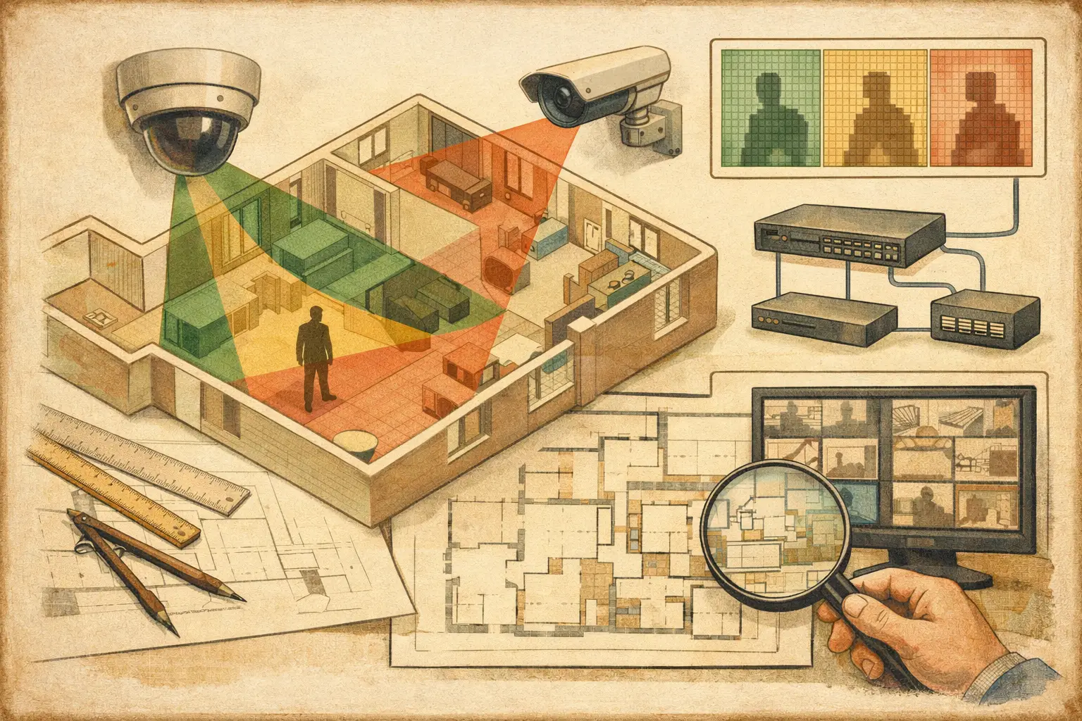
A camera coverage drawing can look technically convincing while being wrong by several feet. If the imported plan is not calibrated correctly, field of view, DORI distances, pixel density, mounting positions, cable routes, and camera counts are all based on false geometry. Knowing how to validate drawing scale is therefore a required early design control, not a formatting task.
Why Drawing Scale Controls CCTV Design Results
CCTV design calculations begin with distance. A camera’s focal length, sensor size, resolution, mounting height, tilt, and direction determine the calculated field of view at a given physical distance. Pixel density in pixels per foot or pixels per meter, often reviewed against a DORI objective, also depends directly on that distance.
If a floor plan is scaled 10% too small, a corridor that appears to be 90 feet long may actually be 99 feet long. The camera selected for identification at the far end may no longer achieve the required pixel density. Conversely, an oversized plan can make coverage appear weaker than it is, leading to unnecessary cameras or inappropriate focal-length selection.
Scale errors also affect more than optical calculations. They can distort the review of wall lengths, door positions, aisle clearances, external perimeters, network cable runs, and the practical relationship between a camera and an occlusion. A scale-calibrated drawing is the common geometric reference that allows security, architectural, and ICT decisions to be reviewed in the same workspace.
Start With a Dimension You Can Defend
The best reference dimension is one that is both clearly labeled on the drawing and unlikely to change during coordination. An overall building dimension, a structural grid span, a surveyed boundary length, or a consistently dimensioned corridor is usually more reliable than estimating a room width from a graphic scale bar.
Use the drawing issue that is closest to the design stage being reviewed. For an early concept design, an architect’s preliminary plan may be sufficient if its limitations are recorded. For detailed design, use the latest coordinated architectural or site drawing available and confirm that revisions have not altered the reference area.
A stated dimension should be treated as the source value, while the imported line between its endpoints becomes the calibration value. For example, if the plan labels a lobby wall as 42 feet 0 inches, draw or select a reference line between the same finished wall faces, then assign that known length. Avoid measuring from thick line edges, furniture symbols, or unclear wall centerlines unless the drawing convention explicitly supports them.
How to Validate Drawing Scale Before Camera Placement
Calibration is only the first step. Validation confirms whether the scale is credible across the drawing, not merely at the line used to set it.
Confirm the Drawing Units and Original Source
First, establish what has been imported. A native CAD file may contain defined drawing units, while a PDF can be exported at a reduced page size, cropped, rasterized, or printed with a scaling setting. An image file may have no usable physical scale at all. The notation “1/8 inch = 1 foot” is meaningful only when the PDF or printed sheet has retained its intended page size.
Do not assume that a scale printed in the title block applies after an export, scan, screenshot, or markup process. In practice, a labeled dimension is more dependable for digital calibration than a nominal drawing scale.
Calibrate Against One Clear Reference
Import the drawing and use a dimension that is easy to identify at both ends. Enter the known real-world length in the platform’s selected units. The resulting scale factor converts all plan geometry into physical distance.
The endpoints matter. If the reference dimension runs between grid lines, calibrate between those grid lines. If it runs between exterior faces, do not substitute internal partition faces. Small endpoint mistakes are amplified across larger site plans.
Check Independent Dimensions in Separate Areas
After calibration, measure at least two additional dimensions that were not used as the reference. Choose dimensions in different portions of the drawing where possible, such as a corridor in one wing and an overall facade or grid span in another.
The measurements should agree with the labeled dimensions within a tolerance appropriate to the drawing type and project stage. A conceptual plan may support less precision than a detailed construction drawing, but visible discrepancies should be investigated rather than ignored. If one area measures correctly and another does not, the source may have been stretched, assembled from multiple drawings, or revised inconsistently.
Test Geometry That Affects Coverage Decisions
Prioritize validation where cameras will be evaluated. Measure a long corridor, a loading-bay approach, a lobby, a vehicle gate lane, or the distance between a proposed camera and the target area. These checks connect scale calibration to the locations where focal length, PPM, DORI, and occlusion decisions will be made.
A plan can pass a short internal measurement yet still fail over a long external distance. This is especially common with scanned drawings, stitched site plans, and documents converted from paper. Use long reference checks when perimeter surveillance, parking areas, or campus paths are in scope.
Recognize When One Scale Does Not Apply
Not every drawing can be calibrated as a single, uniform plane. A site plan may combine an aerial base, a schematic utility layout, and architectural building footprints. A PDF set may place detail drawings at a different scale on the same sheet. Reflected ceiling plans can also be useful for camera coordination but may not accurately represent all wall geometry.
Where separate plans or views are used, calibrate each one independently and label the source drawing, revision, units, and reference dimension in the design record. Do not carry a scale factor from a building plan into a site plan simply because both appear in the same project package.
Perspective images, oblique photographs, and presentation renderings should not be used as primary scale sources. They may help identify operational concerns, such as likely obstructions or sightline changes, but they cannot provide dependable planar geometry without additional survey or model control.
Review Calibration Against Physical Reality
Drawing validation is stronger when it includes an independent reality check. A site walk, laser measurement, verified BIM model, survey data, or a contractor-confirmed structural dimension can expose issues that are not apparent in a PDF.
This does not mean every CCTV concept requires a full survey before design begins. The level of verification depends on the project risk, design stage, and consequence of error. A small office refresh may proceed with controlled assumptions and later field verification. A critical perimeter, transport environment, or multi-building deployment usually justifies tighter geometry control before final camera specifications and installation documentation are issued.
Record assumptions explicitly. If a ceiling height is estimated, distinguish it from a verified mounting height. If a wall was inferred from a plan rather than confirmed on site, identify it as such. Calculated coverage is only as reliable as the geometry and camera inputs behind it.
Common Scale Errors and Their Practical Impact
Several recurring issues deserve attention during design review:
- A PDF was printed or exported with “fit to page” enabled, changing its effective scale.
- A scan has been stretched slightly in one direction, producing inconsistent horizontal and vertical measurements.
- A dimension is read in millimeters while the design workspace is configured in feet, or the decimal separator is interpreted incorrectly.
- A plan includes multiple scales, detail insets, or enlarged areas that are mistakenly treated as one drawing.
- Architectural revisions move partitions, doors, or equipment after the CCTV plan has been calibrated.
The remedy is not always to discard the drawing. Often, the correct response is to isolate the valid area, recalibrate from a verified dimension, revise affected camera positions, and document the new drawing revision. Where geometry remains uncertain, avoid representing calculated PPM or DORI results as confirmed field performance.
Make Scale Validation Traceable
A professional CCTV package should allow a reviewer to understand how the plan was calibrated. Record the source file name or drawing number, revision date, units, reference dimension, calibration location, and independent dimensions checked. Include any limitations that may affect camera installation, such as unverified ceiling levels or areas awaiting architectural coordination.
In CCTV Design Tool Online, the practical workflow is to import and calibrate the drawing before creating walls and camera positions, then review field of view, pixel density, blind spots, coverage overlap, and network topology against the calibrated geometry. If the reference scale changes, revisit the design rather than assuming previously calculated coverage remains valid.
A calibrated plan does not replace a field survey, manufacturer datasheets, installation coordination, or review by qualified professionals. It gives those activities a dependable geometric starting point. When scale is treated as a verifiable design input, camera coverage drawings become clearer to installers, consultants, project owners, and reviewers - and far less likely to create avoidable rework later.