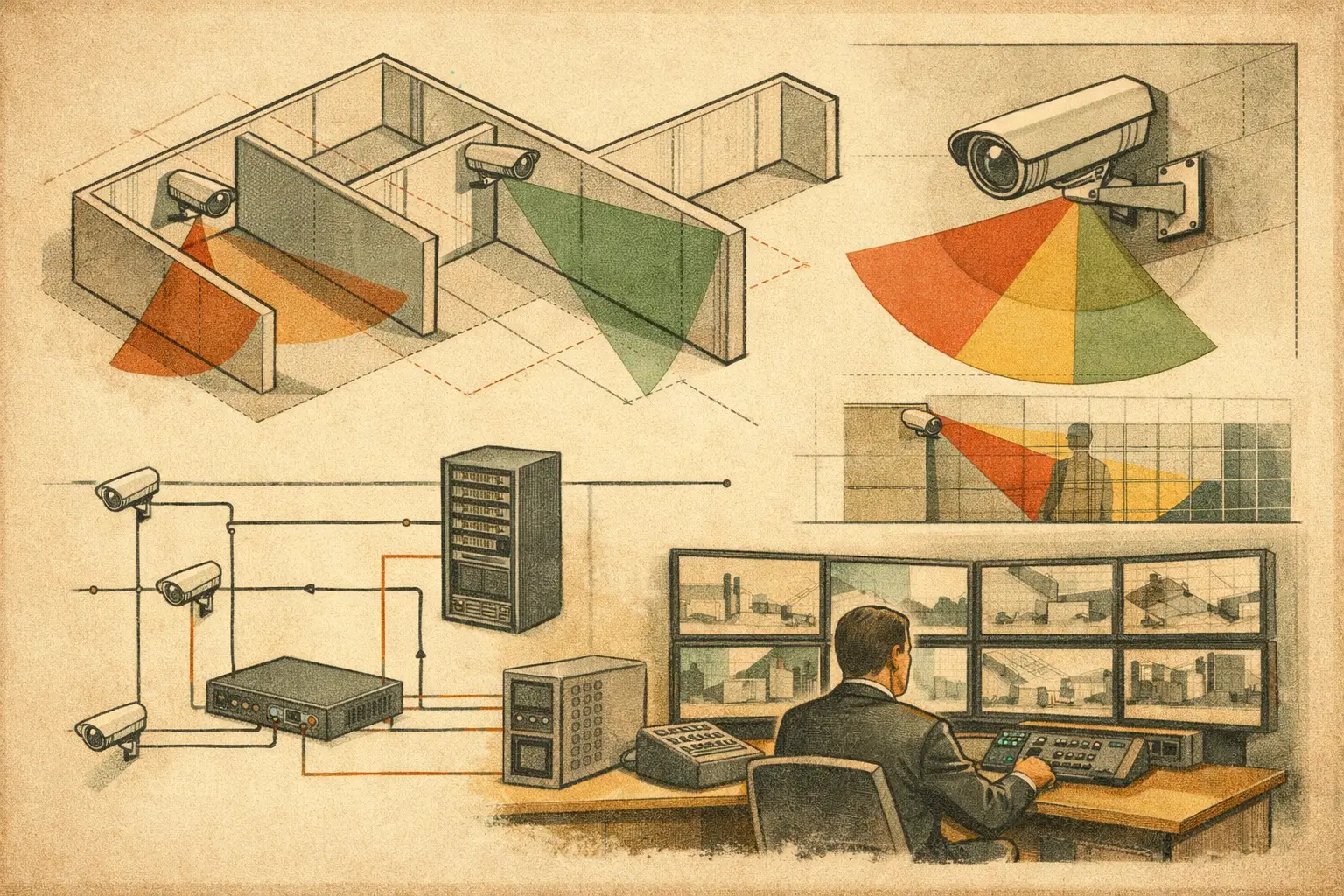
A camera cone that passes through a solid partition may look acceptable on a presentation drawing, yet it represents coverage that cannot exist on site. Wall occlusion in CCTV design is the process of accounting for physical geometry so that a camera field of view stops at walls, columns, doors, racking, and other obstructions. It is a basic requirement for a coverage drawing to be useful during engineering review, installation, and handover.
The issue is easy to miss when teams work from static CAD markups or unscaled floor plans. A wide-angle camera may appear to cover an entire lobby, corridor junction, or warehouse bay, while a short return wall blocks the exact area where recognition is required. The result is not simply a visual defect. It can affect DORI assessment, pixel-density calculations, camera quantities, cable routes, storage assumptions, and the explanation given to a client or reviewer.
Why Wall Occlusion in CCTV Design Changes the Result
A field of view is an optical calculation based on camera location, sensor size, focal length, mounting height, direction, and tilt. Occlusion is a geometry calculation. Both must be considered together.
Without geometry, the design tool projects the full camera cone across the floor plan. With occlusion, the visible area is limited by the first solid object intersected by each line of sight. The difference is particularly significant in buildings with cellular offices, retail shelving, elevator lobbies, stair cores, service corridors, and irregular external facades.
Pixel density only has meaning in areas the camera can actually see. A plan might calculate sufficient pixels per foot or pixels per meter at a doorway beyond a wall, but the wall prevents any usable image from reaching the camera. In that location, the calculated PPM and associated DORI target are not merely lower than expected - they are irrelevant because there is no line of sight.
This distinction matters when specifying objectives. Detection may be appropriate across a broad open area, while recognition or identification is needed at an access door, cash point, gate, or reception desk. If a partition interrupts that view, changing resolution alone will not solve the problem. The camera must be relocated, its viewing direction revised, the obstruction addressed, or another camera introduced.
Treat Walls as Design Inputs, Not Background Graphics
Floor plans often contain visual information that is not ready for CCTV analysis. Walls may be represented by hatches, disconnected lines, furniture blocks, or layers that include structural elements and annotations together. Before positioning cameras, establish which objects are true physical obstructions and which are drafting symbols.
Start by importing the current drawing and completing scale calibration against a verified dimension. This step governs more than camera spacing. Incorrect scale changes the apparent width of a corridor, the distance to a target, the field of view footprint, and the PPM calculation. A wall model built on an incorrectly calibrated plan can still look plausible while producing unreliable outputs.
Next, review wall continuity. Small gaps between line segments can create false sightlines. Overlapping walls, duplicate imports, or boundaries drawn with unusually thick strokes can also change the occlusion result. The goal is not to reproduce every architectural detail. It is to create a defensible representation of the physical geometry that affects camera visibility.
Wall thickness can matter. For a simple plan-view visibility study, a single closed obstruction boundary may be sufficient. Where cameras look through narrow openings, along tight corners, or across door reveals, the actual thickness and placement of a wall affect the available angle. A camera mounted close to a perpendicular wall may lose far more of a corridor than a thin-line drawing suggests.
Openings Need Their Own Review
Doors, glazed partitions, roll-up shutters, turnstiles, and vehicle gates should not automatically be treated as either permanently clear or permanently blocked. Their condition depends on the operational scenario being designed.
A door that is normally closed may block a camera's view into an office. A door intended to remain open during business hours can still obstruct a camera when opened against the wall. A glass partition may provide a line of sight but introduce reflections, glare, tinting, dirt, or low-light effects that a two-dimensional geometry model cannot predict. These conditions should be recorded as design assumptions and verified during the site survey and commissioning process.
The same principle applies outdoors. Landscaping, parked vehicles, perimeter fencing, loading equipment, and seasonal vegetation can all cause practical occlusion. A floor plan or site plan may identify permanent walls accurately while omitting operational obstructions. Geometry analysis provides calculated visibility based on the modeled environment, not a guarantee of live scene performance under every condition.
Build Coverage From the Target Backward
A reliable workflow begins with the required observation point rather than the camera symbol. Identify the target: a person entering a door, a vehicle lane, a transaction point, a corridor approach, or a boundary crossing. Define the required DORI objective and the applicable project pixel-density criterion. Then test whether a proposed camera has an unobstructed line of sight to that target.
For a door, assess more than the door center. Consider the approach path, the face position likely to be captured, and the area immediately before and after the threshold. A camera looking obliquely across a hallway may cover the opening on paper but miss a face behind a return wall until the subject has passed the critical point.
For corridors, examine the full usable width. Cameras mounted at one end can be efficient, but wall projections, fire-door recesses, and cross-corridor intersections often create blind spots. A second camera may provide better coverage overlap than selecting a wider lens. Wider focal lengths expand the field of view but reduce pixel density at distance and can introduce greater perspective distortion.
For open spaces, use occlusion to distinguish actual blind spots from simply lower-density areas. A large atrium may be visible from several cameras, but a column cluster can produce narrow shadow zones that are difficult to identify without modeled geometry. Overlap should be purposeful. It can support continuity of observation at critical routes, but excessive overlap may increase camera count without improving the defined security objective.
Resolve the Geometry Before Adjusting the Camera Specification
When an obstruction interrupts the view, teams sometimes respond by increasing resolution or selecting a camera with a different lens. Those changes can improve image detail in visible areas, but they cannot see through a wall. Address the physical line of sight first.
Relocation is often the most effective option. Moving a camera a short distance from a wall or changing its mounting height can open a sightline around a corner. However, a higher mounting position can make facial capture more difficult because of the steeper viewing angle. Changing tilt can recover some of the target area, but may increase foreground distortion or reduce usable detail at the far end of the scene.
A different focal length can narrow the scene around a target after the line of sight is established. This may improve PPM where recognition or identification is required, but it also reduces situational coverage. Adding a second camera is appropriate when one device cannot satisfy both a wide-area detection role and a detailed target role without unacceptable compromises.
The decision should be traceable. Record the camera position, mounting height, focal length, sensor size, direction, tilt, modeled obstruction, target distance, and required performance criterion. This allows another designer, installer, or project reviewer to understand why a camera was selected and what assumptions should be checked on site.
Verify the Model at Three Levels
A practical design review should test geometry, optical performance, and installation reality together. First, confirm that walls and openings correspond to the latest architectural information. Second, review the occlusion-limited field of view alongside DORI or PPM outputs. Third, assess whether the proposed mounting point is physically possible, considering ceilings, structural members, containment routes, maintenance access, and likely scene changes.
This is also the point to coordinate with related disciplines. A camera shifted to clear a wall may require a longer cable route, a different PoE budget calculation, or an adjustment to the network topology. The camera schedule, floor plan, coverage analysis, and report should be updated together. Disconnected deliverables are a common source of installation rework because each document can retain a different version of the camera position.
CCTV Design Tool Online supports this workflow by keeping calibrated drawings, walls, camera parameters, occlusion-aware coverage, DORI analysis, and report outputs in one design workspace. The calculated result still requires professional review, particularly where drawings are incomplete, geometry is complex, or project requirements are jurisdiction-specific.
Use Occlusion Findings as Coordination Evidence
The value of wall modeling is not limited to finding defects. It gives the project team a clear basis for decisions. A visible blind spot can support a request to reposition a camera, provide an additional device, alter a partition, or revise the security requirement before installation starts.
Reports should show the occlusion-limited coverage rather than a generic cone over the plan. Where a critical area remains blocked, label it clearly and state the proposed treatment or residual limitation. This is more useful than implying continuous coverage that the design cannot deliver.
The most effective CCTV drawings do not show the largest number of camera cones. They show where the camera can truly see, what level of detail is calculated at the target, and which site conditions still need verification before the system is installed.