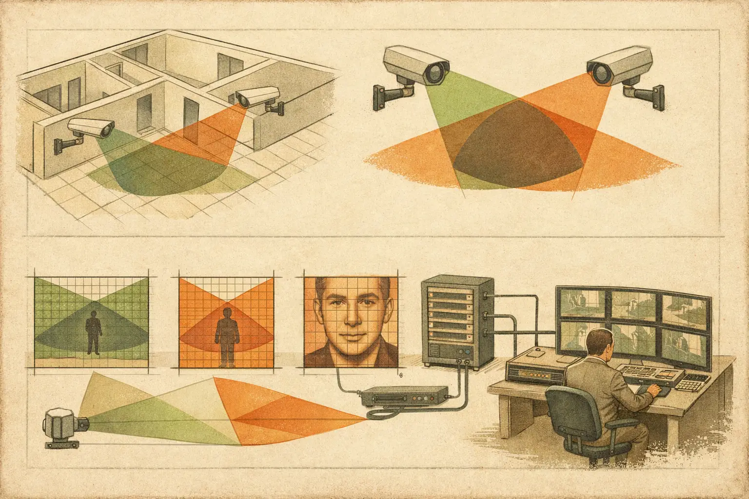
A camera plan can show every area covered and still fail operationally at the moment an incident crosses from one view to another. The question of when should camera views overlap is therefore not about filling a drawing with intersecting camera cones. It is about preserving usable observation, identification, and scene continuity where one camera alone has a known limitation.
Coverage overlap has a cost. It can increase camera count, recording storage, network load, installation complexity, and review time. The right design does not maximize overlap everywhere. It applies it deliberately at handoff points, high-risk locations, areas affected by occlusion, and places where the required DORI outcome cannot be maintained by a single view.
What camera coverage overlap actually means
Camera coverage overlap is the shared area visible to two or more cameras. In a design drawing, it is often represented by the intersection of field-of-view polygons. That is useful, but it is only the first layer of analysis.
A meaningful overlap exists only where both cameras provide a usable view of the relevant target. For example, two cameras may both see a corridor junction, yet one may provide only detection-level pixel density while the other provides recognition-level coverage. Their visual cones overlap, but their operational value is not equivalent.
Review overlap at the target plane and against the project objective. That requires the camera resolution, sensor size, focal length, mounting height, direction, tilt, scene distance, and required pixel density to be considered together. It also requires walls, doors, partitions, shelving, structural columns, and other physical geometry to be modeled as potential occlusions.
When should camera views overlap?
At transitions between surveillance zones
The most common reason for overlap is to avoid losing continuity as a person, vehicle, or object moves from one camera's area into another. This is especially relevant at corridor intersections, building entrances, vehicle gates, reception approaches, loading bays, stair landings, and perimeter routes.
Without overlap, there may be a gap between the effective edges of two views. Even where there is no literal blind spot, the subject can leave one scene before becoming clearly visible in the next. A small shared zone gives operators and investigators a visual handoff. It helps establish direction of travel, timing, clothing, carried items, and the relationship between events in adjacent areas.
The required overlap length depends on movement speed and the purpose of the view. A pedestrian corridor generally needs less shared coverage than a roadway or logistics lane where vehicles move quickly. In either case, assess the overlap in real-world dimensions after scale calibration, not simply as a percentage of two camera cones on an uncalibrated drawing.
Where identity or transaction evidence must be corroborated
Some locations benefit from two views because a single camera may not capture every evidential detail. At an entrance, one camera may cover the overall approach while another provides a tighter frontal view near the threshold. At a reception desk, a contextual camera can show the wider interaction while a second camera protects facial detail at the service point.
This is not duplication for its own sake. The cameras should have distinct roles. One may support recognition or identification at a defined target distance, while the other records the wider sequence of events. If both cameras are aimed at the same plane from nearly the same angle and provide the same pixel density, the second device may add limited operational value.
Different viewpoints can also reduce the risk that a cap, face covering, glare, backlighting, or a person's orientation makes the primary view less useful. The design objective should state what each camera is expected to deliver, rather than assuming that two views automatically create better evidence.
Around occlusions and complex geometry
Occlusion is a central reason to introduce overlap. Field-of-view calculations that ignore walls and physical objects can imply coverage that does not exist in the installed environment. A corridor camera may appear to see a doorway, for example, while the door leaf, soffit, column, or internal partition prevents a usable view of the threshold.
Overlap is particularly valuable in retail aisles, warehouse racking, multilevel parking structures, campuses, industrial yards, and spaces with frequent changes in layout. A second viewpoint can cover the shadow created by fixed geometry or provide continuity if temporary objects block part of the primary view.
Do not treat overlap as a substitute for reviewing obstructions. First, model the known geometry and identify the blind spot. Then determine whether camera repositioning, a different focal length, a revised mounting height, or an additional camera is the most effective response. Adding another wide-angle camera may create a larger overlapping area but still fail to deliver the necessary PPM at the point of interest.
At the edge of a DORI requirement
DORI analysis helps distinguish visual presence from usable detail. A scene may meet detection requirements at the edge of a camera's field of view but fall short of recognition or identification requirements. Where a person moves through that boundary, overlap can preserve the required pixel density across the transition.
This is common at entry paths, secure doors, turnstiles, cash-handling areas, and vehicle access points. A wide contextual camera may cover the full scene, while a second camera maintains the specified detail level at the critical zone. The overlap should occur where the higher DORI requirement applies, not merely where the camera cones happen to intersect.
Pixel density should be evaluated using the camera's configured specification and the physical dimensions of the target area. Calculated PPM is a design result. Actual image performance can still be affected by lighting, motion blur, compression, focus accuracy, lens quality, scene contrast, and recorder configuration.
When overlap is unnecessary or inefficient
Not every boundary requires two cameras. In low-risk open areas, a single correctly selected camera may provide the required coverage and DORI result without a second view. Excessive overlap can make a design harder to justify, increase infrastructure requirements, and create repetitive footage with little additional value.
Overlap may also be inefficient when cameras share the same mounting location, direction, and scene constraints. If glare, direct sunlight, or an obstruction compromises one view, a nearly identical second view may be compromised in the same way. A more useful design may place the supporting camera at a different angle, height, or side of the route.
There is also a network planning consideration. Each additional camera affects switch port allocation, Power over Ethernet capacity, uplink bandwidth, storage sizing, rack space, and network topology. Design decisions should be traceable from the coverage need through to the camera schedule and infrastructure plan.
How to set practical overlap in a CCTV design
There is no universal overlap percentage that suits every project. A fixed rule such as 10% or 20% can be a starting convention, but it is not an engineering answer. The appropriate amount depends on the target, movement path, camera angle, required DORI level, and the consequences of losing continuity.
Start by defining the operational purpose of the shared zone. Is it intended to hand off a person between corridors, confirm an entry event, observe a vehicle turning, or protect a known blind spot? That purpose determines the required usable dimensions of the overlap.
Next, position cameras using calibrated floor plans or site geometry. Confirm mounting height, tilt, lens focal length, sensor size, and direction. Then review the resulting field of view with physical walls and obstructions included. A cone that crosses a wall should not be counted as coverage on the other side of it.
Evaluate pixel density separately for each camera in the shared area. If the requirement is recognition, both cameras do not always need to achieve recognition across the entire overlap. One may provide the primary recognition view while the other supports context and continuity. What matters is that the documented design intent is clear.
Finally, test the design against realistic paths of travel. Consider a person entering through a door, walking around a corner, moving behind a column, or approaching a controlled point from the less obvious direction. This often exposes gaps that are not visible when reviewing each camera in isolation.
Document overlap as a design decision
A professional design deliverable should show more than camera locations. It should identify camera identifiers, coverage areas, blind spots, key target zones, DORI or PPM results, mounting assumptions, and relevant physical constraints. Where overlap has been included, document why it exists.
For example, a note such as “CAM-12 and CAM-13 provide continuous pedestrian coverage through the lobby-to-corridor transition” is more useful to installers and reviewers than an unexplained pair of intersecting view polygons. It creates traceability when the design is revised after architectural, operational, or equipment changes.
CCTV Design Tool Online can support this workflow by allowing designers to calibrate drawings, place cameras using technical parameters, visualize fields of view against modeled geometry, review overlap and blind spots, and produce structured project documentation. The resulting calculations remain design guidance and should be verified against the final site conditions, camera datasheets, lighting environment, and project requirements.
The best overlap is the one that answers a specific operational risk. Define the handoff, obstruction, or critical target first, then verify that the shared coverage provides usable detail from a realistic viewpoint. That discipline produces a camera layout that is easier to install, review, and defend long after the drawing is issued.