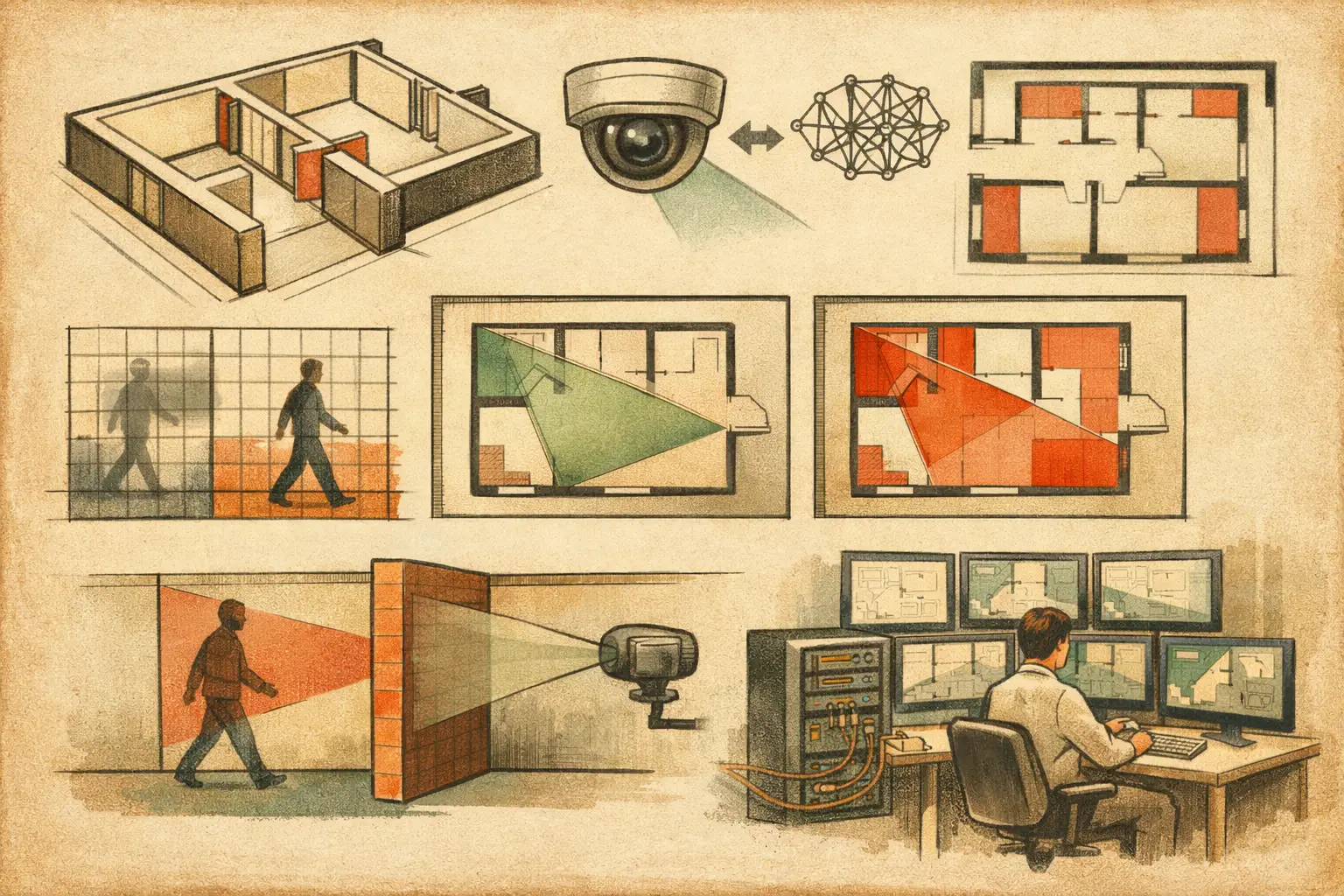
A camera coverage drawing can look convincing while missing the physical condition that matters most: a corridor wall, glazed partition, fire door, rolling shutter, or service-room enclosure that blocks the intended view. AI wall detection for floorplans can reduce the time needed to prepare a drawing, but it does not remove the engineering task of confirming what the model has recognized and how that geometry affects CCTV performance.
For security consultants, installers, architects, and enterprise security teams, the value is not simply faster linework. It is the ability to establish a usable physical model earlier, so field of view, occlusion, pixel density, DORI targets, cable routing, and report outputs can be reviewed from the same coordinated design workspace.
What AI Wall Detection for Floorplans Actually Does
AI-assisted wall detection analyzes an imported floor plan and identifies visual patterns that are likely to represent walls, partitions, room boundaries, doors, and other architectural features. Depending on the drawing quality, it may convert these detected features into editable geometry or provide a basis for quicker tracing and review.
This is particularly useful when a project begins with a PDF, scanned plan, image export, or a drawing received from another discipline. Instead of manually recreating every perimeter and internal partition, the designer can begin with an AI-generated interpretation and focus attention on verification.
The important distinction is between detected geometry and verified geometry. A detected line is an interpretation of pixels in a source document. A verified wall is a design object that the engineer has checked against drawing notes, room use, elevations, site conditions, and project coordination information. Only the second should be relied on when assessing camera occlusion.
AI is generally more effective on clean, high-contrast drawings with consistent line weights and recognizable symbols. It is less dependable when plans contain raster artifacts, low-resolution scans, dense furniture layouts, revision clouds, hand markups, overlapping disciplines, or inconsistent architectural conventions. A reflected ceiling plan, for example, may visually resemble a floor plan while representing a different set of conditions relevant to camera mounting and cable pathways.
Why Wall Geometry Changes CCTV Design Results
A camera's field of view is not a guarantee that every point inside the visible cone can be observed. A field-of-view calculation describes the optical area projected from camera specifications such as sensor size, focal length, mounting height, direction, and tilt. Walls and other physical obstructions determine which parts of that calculated area remain visible.
This difference becomes critical in common design scenarios. A wide-angle camera at a lobby ceiling may provide broad visual coverage, but a reception counter, glazed meeting room, or structural column can create occluded areas. In a warehouse, racking and equipment may be more significant than the external wall perimeter. In a corridor, door swings and return walls can create blind spots near entrances even where the camera cone appears to cover the full corridor width.
Wall geometry also affects where coverage overlap is useful. Two cameras may overlap on a drawing because their fields of view intersect, yet a partition may prevent either camera from seeing the same operational area. Conversely, a well-positioned overlap at a doorway can support a more reviewable transition between spaces. The design objective depends on the required observation task, not simply on maximizing the colored area on a plan.
Pixel density must be considered separately. PPM and DORI calculations can indicate whether a camera configuration is expected to provide a specified identification, recognition, observation, or detection level at a given distance. However, those calculations apply to the unobstructed visual path represented in the model. If a wall blocks the path, the calculated pixel density beyond that wall has no practical value.
A Practical Verification Workflow
The most reliable use of AI detection is as a controlled first pass within a structured design workflow. Import the drawing at its best available quality, then calibrate scale before relying on measured distances, focal-length selection, or coverage results. A clean wall model at the wrong scale can still produce misleading field-of-view and pixel-density outputs.
Start With the Source Drawing
Review the plan title, revision status, drawing scale, and the disciplines shown before processing it. Architectural floor plans are usually the strongest starting point for wall detection, but they may not show ceiling-mounted features, security grilles, shelving, or temporary partitions. If the CCTV design depends on these elements, obtain the relevant coordination drawings or confirm them through a site survey.
Where a drawing is scanned, check for skew, image compression, missing edges, and inconsistent scaling. A single known dimension is helpful for scale calibration, but a second independent measurement provides a useful cross-check. If two known dimensions do not align after calibration, the source may be distorted or may not be drawn at a uniform scale.
Review Detected Walls and Openings
After AI-assisted detection, inspect the model room by room. Confirm external walls, internal partitions, shafts, stair enclosures, reception counters, and other high-impact obstructions. Then review openings carefully. A door opening should not be modeled as solid wall, while a closed or security-controlled door may affect the operational view differently from an open passage.
Glazing deserves specific attention. A glass partition may be physically transparent under normal conditions, but reflections, lighting contrast, privacy film, frosting, blinds, and camera angle can reduce usable image quality. It should not automatically be treated as equivalent to an open line of sight. The design model should reflect the intended analytical assumption, and that assumption should be documented for review.
Not every visible line belongs in the wall layer. Furniture, cabinets, workstation clusters, hatch patterns, dimension strings, and electrical symbols can be misread by automated detection. Remove or reclassify false geometry before it influences occlusion analysis. Conversely, add physical items that are absent from the plan but material to the camera view, such as full-height storage, machinery, access-control turnstiles, or perimeter fencing.
Position Cameras After Geometry Review
Once walls and key obstructions are verified, position cameras based on operational objectives. Set the camera direction, mounting height, tilt, focal length, sensor size, and resolution using the available technical parameters. Then inspect the field of view alongside the occlusion model rather than treating the camera cone as a final answer.
A useful review asks direct questions: Can the camera see the face approach path at the required pixel density? Does a door leaf block the view at a critical moment? Does a corner create a blind spot near a cash-handling point, elevator lobby, or escape route? Is the proposed mounting height realistic for the ceiling construction and maintenance access?
This process often leads to design choices that an unverified automated layout would miss. A narrower focal length may improve pixel density at a target point but reduce contextual coverage. A second camera may resolve a blind spot but add network load, switch-port demand, storage implications, and coordination requirements. There is no universally correct camera density. The appropriate solution depends on risk, operational task, site geometry, lighting assumptions, and client requirements.
Where Human Review Remains Essential
AI can accelerate the repetitive part of floor-plan preparation, especially on large multiroom facilities. It cannot reliably infer all construction details or operational conditions from linework alone. It may not distinguish a full-height wall from a low partition, identify whether a room will be reconfigured, or understand that a camera's target is a controlled doorway rather than the entire room.
Professional review should also connect the floor-plan model to related design disciplines. Network topology may influence camera locations where PoE distance, cabinet position, cable containment, or resilience requirements constrain the preferred placement. Architectural coordination may alter a mounting location. A site walk may reveal signage, lighting fixtures, sprinkler heads, or structural elements that are not represented accurately in the drawing.
CCTV Design Tool Online supports this disciplined approach by keeping imported plans, calibrated scale, editable physical geometry, camera specifications, field-of-view analysis, DORI and PPM review, and reporting outputs within one browser-based workspace. The calculation results provide design evidence for discussion and coordination, but they remain dependent on the quality of the inputs and must be reviewed by qualified project professionals.
Make Verification Traceable
For projects involving multiple reviewers, record the assumptions that materially affect coverage. Note the drawing revision used, scale-calibration references, areas where wall geometry was manually corrected, assumed door positions, and any site conditions pending confirmation. This is more useful than presenting an automated output as final because it tells installers, clients, and reviewers where the design is firm and where coordination is still required.
When plans change, update the geometry before revising camera positions or issuing a report. A relocated partition or newly enclosed room can invalidate a coverage claim even if every camera remains in the same place. Treat wall data as an engineering input that evolves with the project, not as background artwork.
The strongest use of AI wall detection is therefore modest and practical: let it shorten the path from drawing import to a reviewable model, then apply professional judgment where the project carries consequences. A verified wall line may take seconds to correct, but it can prevent an avoidable blind spot from reaching the installation stage.