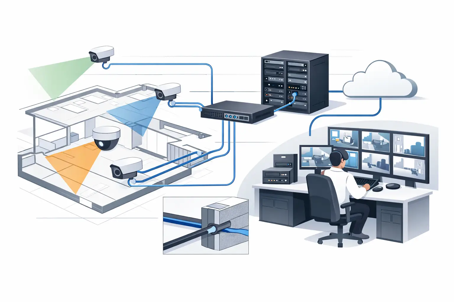
A camera layout can look complete on a floor plan and still fail at the coordination stage if the cable path has not been designed. CCTV cable routing is where coverage design becomes an installable system: every camera needs a practical route back to its network switch, power source, recording infrastructure, or local field enclosure. The route affects cable length, containment capacity, electrical separation, firestopping, access for maintenance, and the amount of rework required on site.
For security consultants, integrators, and project teams, routing should not be treated as a final annotation added after camera positions are approved. It is a design input that can change camera selection, network topology, cabinet locations, and even the suitability of a proposed mounting point.
Start CCTV Cable Routing After Camera Geometry Is Credible
Cable planning should begin once the camera design has a defensible physical basis. Confirm the field of view, focal length, sensor size, mounting height, tilt, and direction first. Review whether walls, soffits, glazing, shelving, doors, or other physical geometry create occlusion or blind spots. A camera moved several feet to improve DORI performance may require a substantially different route or a different containment strategy.
The first routing input is not simply a camera count. It is a coordinated camera schedule that identifies each device location, mounting type, network requirement, power method, and expected connection point. A fixed indoor dome supplied by Power over Ethernet may need one horizontal cable run. A PTZ camera, an external IR illuminator, or a device with local power can introduce additional circuits and termination requirements.
At this stage, distinguish calculated outputs from site conditions. A calibrated floor plan can provide useful route-length estimates, but it cannot confirm whether a ceiling void is accessible, a riser is congested, or a structural beam blocks a proposed path. These matters require review against current architectural, electrical, mechanical, and construction information.
Map Pathways Before Measuring Cable Length
A direct line between a camera and a communications room is rarely the cable route. Routing should follow available pathways: ceiling containment, cable tray, conduit, basket, raised floor systems, wall cavities, risers, external ducts, and protected transitions between buildings. Draw the actual intended route, including vertical changes, rather than relying on straight-line plan distances.
A useful routing drawing identifies the camera, the containment path, the nearest consolidation or connection point where applicable, and the destination switch or cabinet. It should also show transitions through walls, floors, and fire-rated barriers so they can be coordinated with the relevant building disciplines.
For complex sites, divide the route into segments. A camera may run from a ceiling mount to a local tray, along a corridor tray, down a riser, across a communications room pathway, and then into a rack. Segmenting the path makes assumptions visible. It also helps installers understand where access equipment, drilling, sleeves, supports, or firestopping coordination may be needed.
Include Vertical Distance and Service Allowance
A common design error is measuring only the horizontal plan distance. Add mounting drops, ceiling rises, riser travel, cabinet entry, and reasonable service allowance at equipment locations. The correct allowance depends on the installation method and project requirements, but the principle is consistent: allow enough cable for safe termination, future servicing, and orderly dressing without creating unmanaged loops.
Do not convert a drawing estimate directly into a procurement quantity without review. Cable quantities should account for route complexity, approved containment, installation practice, and project-specific waste factors. The final installed length should be verified during delivery and testing.
Check Distance, Power, and Network Topology Together
Cable routing has a direct relationship with network design. Copper Ethernet channels have defined performance limitations that must be assessed using the applicable cabling standard, the selected cable type, patching arrangement, and manufacturer guidance. A route that appears acceptable on a plan can become unsuitable once patch leads, service loops, intermediate connection points, and vertical travel are included.
Where estimated runs approach the practical limit for the chosen architecture, consider whether a local PoE switch, fiber uplink, field cabinet, or revised telecom room location is more appropriate. This is not automatically the best answer. A field switch can reduce copper distance but introduces requirements for power, enclosure selection, environmental suitability, UPS strategy, maintenance access, and network resilience.
Power budget matters as much as distance. Confirm the expected device load using verified manufacturer data, especially for cameras with heaters, blowers, integrated illumination, motorized lenses, or PTZ functions. Then review switch PoE capacity at the port and total-switch level. A camera may be within cable-distance limits but still exceed the available PoE budget during a high-load operating condition.
Network topology should be documented alongside routes. Identify the switch serving each camera, uplink path, rack or enclosure, and any proposed redundancy. This creates traceability between the camera schedule, cable labels, switch-port schedule, and final test records.
Coordinate Separation, Containment, and Building Interfaces
Security cabling should be coordinated with electrical, ICT, fire, and mechanical systems before installation begins. The required separation from power circuits, the use of shared containment, and the protection method at crossings depend on the applicable electrical and cabling requirements, building conditions, and authority having jurisdiction. These decisions should be verified by qualified professionals rather than inferred from a generic CCTV drawing.
Avoid treating containment as unlimited empty space. Tray fill, bend radius, pull tension, support spacing, accessible routes, and future capacity all affect whether a route is practical. A crowded pathway may lead to damaged cable, difficult fault finding, or later changes that disrupt live systems.
Penetrations require equal attention. Where security cables cross walls, floors, or compartment boundaries, the design team should identify the location and coordinate the required sleeve, pathway, and firestop approach with the responsible trades. CCTV designers should show the need for the penetration; approved construction details and installation responsibility must follow the project specification and local requirements.
Outdoor routing adds another layer of design review. Consider UV exposure, moisture ingress, temperature range, physical protection, drainage, lightning-risk strategy where relevant, and transition points between external and internal pathways. The selected cable and enclosure must be appropriate for the environment based on verified product documentation.
Use Routing to Challenge Camera Locations Early
The best optical position is not always the best installation position. A camera may have strong pixel density at a doorway but require an exposed external conduit route, access above a hard ceiling, or a cable run beyond the selected network architecture. Conversely, a slightly revised mounting location may preserve required DORI coverage while using an accessible tray route and reducing installation complexity.
This is why camera placement, coverage overlap, and cable routing should be reviewed together. Do not move cameras solely to shorten cable runs if the move creates blind spots, problematic angles, or insufficient PPM at the target area. Equally, do not retain a theoretically ideal camera position without documenting the infrastructure needed to support it.
In a browser-based design workspace such as CCTV Design Tool Online, teams can use calibrated drawings and physical geometry to review camera coverage while recording the intended network path and equipment locations in the same project context. That improves coordination, but it does not replace site verification, cable surveys, or professional review of installation constraints.
Produce a Route Package the Site Team Can Use
A usable routing deliverable should be more than colored lines on a plan. It needs enough information for the installer, project manager, and reviewer to understand intent and identify unresolved dependencies. At minimum, coordinate the following information:
- Camera identifier, location, mounting type, and serving switch or cabinet
- Proposed pathway and route segments, including risers and major transitions
- Estimated route length and any runs needing distance or power-budget review
- Cable type, where it is defined by the project specification or approved design
- Penetrations, containment interfaces, field enclosures, and access constraints
- Labeling references that align with the camera schedule, rack schedule, and test documentation
Keep assumptions visible. Mark routes as proposed where containment has not been confirmed, and log actions such as "verify ceiling access" or "confirm tray capacity with electrical contractor." This is more valuable than presenting an overconfident drawing that conceals coordination risk.
Review Changes as Controlled Design Changes
Cable routes often change after construction coordination, ceiling coordination, or client revisions. When they do, review the impact beyond the drawing line. A route change can affect cable length, PoE performance, switch assignment, containment loading, equipment access, and the labeling schedule.
Treat these as controlled design changes. Update the route drawing, camera schedule, network topology, and report together where relevant. This preserves a traceable record of what was designed and why. It also reduces the familiar site problem of a camera plan, cable schedule, and switch-port list that no longer describe the same system.
Well-planned routing is not invisible administrative work. It is the practical connection between a calculated field of view and a maintainable security installation. When route assumptions are documented early and reviewed with the building team, the project gains a clearer path from design intent to field verification.