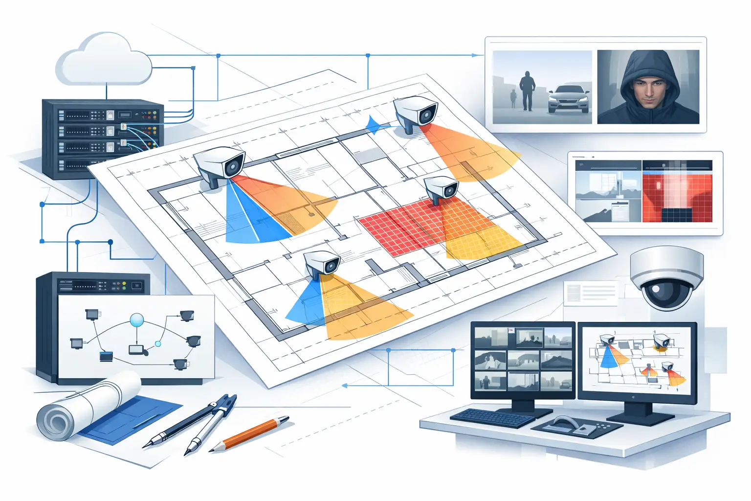
A camera symbol placed on a drawing is not yet a CCTV design. It may communicate an intended location, but it does not establish what the camera can identify at a target distance, whether a wall blocks its view, or whether the network can support it. CCTV floor plan software turns the floor plan into an engineering workspace where those questions can be tested and documented before installation.
For security consultants, integrators, architects, and project owners, this distinction matters most when a project changes. A revised partition layout, ceiling height, entrance position, or camera requirement can affect coverage, cabling, recorder capacity, and the camera schedule at the same time. A disciplined digital workflow makes those dependencies visible rather than leaving them spread across CAD files, screenshots, spreadsheets, and manually edited reports.
What CCTV Floor Plan Software Should Do
The core purpose of CCTV floor plan software is to connect the physical layout of a site to camera performance requirements. A useful platform begins with an imported plan, but it should go substantially further than placing icons and drawing approximate cones.
First, the drawing needs scale calibration. A floor plan that is even slightly out of scale can create misleading distance, field-of-view, and pixel-density results. The user should identify a known measurement on the drawing, such as a dimensioned corridor or structural grid, and use it to establish the working scale. This provides the spatial basis for camera placement and coverage analysis.
The next requirement is geometry. Walls, doors, glazed partitions, columns, racking, counters, and other site features influence what a camera can see. A field-of-view graphic that passes through a solid wall may look persuasive in a presentation, but it does not represent an achievable view. The design workspace should therefore allow the team to create or review physical obstructions and assess occlusion as part of the coverage calculation.
Camera placement must also be tied to technical inputs. Resolution alone is not enough. Sensor size, focal length, mounting height, direction, tilt, and the required task at the target all change the practical result. When these inputs are captured consistently, the plan becomes a traceable design record instead of a visual estimate.
From Camera Location to Usable Coverage
A camera’s field of view answers one question: what area falls within the image? It does not, on its own, answer whether the image contains sufficient detail for the intended security task.
That is where pixel density and DORI become valuable. Pixels per meter, or PPM, describe the available image detail across a real-world distance. DORI provides a common framework for considering detection, observation, recognition, and identification tasks. The correct target depends on the operational requirement. Monitoring vehicle flow at a site entrance is different from recognizing a person at a controlled doorway, and both are different from identifying a person at a critical access point.
A sound workflow defines the required task before treating a camera position as acceptable. The designer can then review the area where the selected camera, lens, and mounting configuration meets the intended PPM or DORI threshold. This is more useful than treating every part of a room as if it requires the same level of detail.
There are trade-offs. A wider focal length can cover more area, but image detail falls more quickly as distance increases. A longer focal length can improve detail at a target, but may introduce blind spots closer to the camera or create a narrower view that misses approach paths. Increasing resolution may improve calculated pixel density, but it can affect bandwidth, storage, and equipment selection. The right answer depends on the threat model, site layout, operational procedures, lighting conditions, and verified camera specifications.
Calculated results are design guidance, not a promise of field performance. Image quality can be influenced by illumination, scene contrast, compression settings, motion, lens quality, installation tolerance, and manufacturer-specific processing. These factors should be reviewed during commissioning alongside the approved design intent.
Model Occlusion Before It Becomes Rework
Blind spots are not always obvious in a two-dimensional drawing. A reception desk may block a lower viewing angle. A doorway may open into a camera’s intended path. Warehouse racking can create repeated occlusion zones. In external areas, fences, gates, landscaping, and parked vehicles can alter the effective view.
This is why wall and obstruction modeling should be a normal stage of the design process, not a finishing exercise. Once geometry is in place, the designer can compare the theoretical field of view with the visible field of view after occlusion. The difference often explains why a camera arrangement that appears adequate in a presentation fails to cover a critical route in reality.
Coverage overlap also needs judgment. Overlap can provide continuity at doorways, handover between zones, or resilience if one camera is obstructed or offline. However, overlap is not automatically beneficial. Excessive duplication can increase camera counts, bandwidth, and review complexity without improving the required task coverage. The design objective is intentional overlap at operationally important locations, not maximum overlap everywhere.
Treat openings differently from walls
A plan should not assume that all lines represent the same physical barrier. Doors, windows, open archways, and glazed partitions have different effects on sightlines and may require separate treatment. Their real behavior also depends on how the site will operate. A door shown open on an architectural drawing may normally remain closed, while a service entrance may be held open during business hours.
The design record should identify these assumptions. That gives reviewers a clear basis for challenging or confirming the coverage model before the installation team is on site.
Plan the Network Alongside the Cameras
Camera placement decisions create network consequences. Each camera requires a route to power, switching, recording, or edge storage, depending on the project architecture. If network planning is deferred until after the visual layout is accepted, the team may discover difficult cable routes, congested communications rooms, insufficient switch capacity, or impractical segmentation requirements.
A floor plan workspace should help the security and ICT disciplines coordinate early. The design team can associate cameras with network devices, consider topology, and review how camera groups relate to cabinets, switches, and recording infrastructure. The output does not replace a detailed network engineering review, but it creates a clearer handoff between disciplines.
Bandwidth and storage calculations should be based on the selected camera configuration and project assumptions, including resolution, frame rate, codec, scene activity, retention requirement, and recording mode. These values should be verified against current manufacturer documentation and the project’s actual recording architecture. A generic bitrate assumption may be acceptable for early feasibility work, but it should not be treated as a final commissioning value.
Produce a Deliverable People Can Review
A design is easier to approve internally when the evidence is organized. Instead of sending a client a floor plan with untested camera cones, the team can produce a structured deliverable that explains the design inputs, camera schedule, coverage logic, DORI or PPM criteria, blind-spot assumptions, and network relationships.
This is particularly useful on multi-stakeholder projects. Architects need to understand mounting and coordination implications. Contractors need locations and routes they can build from. Security managers need confidence that critical routes and assets were considered. Project owners need a record of what the proposed system was designed to achieve.
CCTV Design Tool Online supports this workflow in a browser-based environment: import and calibrate the drawing, review walls and geometry, configure cameras using technical parameters, assess fields of view and pixel-density coverage, then generate a structured technical deliverable. Because the approach is brand-agnostic, the design can be developed around verified optical and operational requirements rather than a single manufacturer catalog.
A Practical Design Sequence
Start by confirming the latest architectural background and a reliable reference dimension. Import and calibrate the drawing before placing cameras. Next, review walls, openings, fixed obstructions, and important changes in elevation or mounting conditions. Identify security objectives by zone, then define the required task at each target area.
Place candidate cameras using realistic mounting height, focal length, sensor size, direction, and tilt. Review visible coverage, not just the unconstrained cone. Check DORI or PPM at relevant targets, then refine positions and lens selections where the results do not meet the stated objective. After that, assess intentional overlap, likely blind spots, network topology, and the camera schedule.
Finally, document assumptions that cannot be fully resolved from the drawing. These may include final ceiling construction, furniture layouts, lighting design, gate positions, or operational procedures. Design assumptions are not weaknesses when they are visible and assigned for verification. They are far safer than assumptions hidden inside an unannotated plan.
The value of a well-built CCTV floor plan is not that it makes the design look more technical. It gives every project participant a shared, reviewable explanation of what each camera is intended to achieve, what may affect that result, and what still needs verification on site.