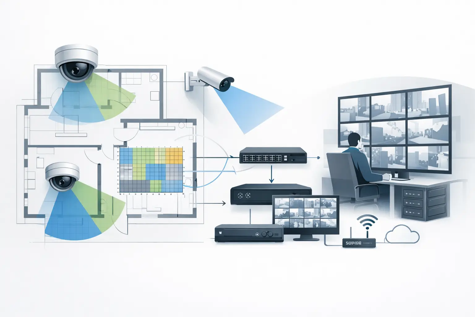
A camera schedule can look complete while the network behind it is undersized, poorly segmented, or impossible to maintain. CCTV network planning is the discipline that turns camera coverage into a system that can transport, record, retrieve, and display video when operators need it. It begins before switches are selected, because resolution, codec, frame rate, scene activity, retention requirements, and physical cable routes all affect the result.
The practical objective is not simply to calculate a total bitrate. A usable design must account for peak traffic, power delivery, uplink contention, storage write performance, resilience expectations, and the path from each camera to the recording and viewing environment. These decisions should remain traceable to the camera design and project requirements.
Start CCTV Network Planning With Verified Camera Inputs
Network calculations are only as credible as the camera inputs. Start with the intended camera specification at each location: resolution, frame rate, compression method, operating mode, and expected bitrate range. A 4K camera at a quiet indoor doorway may generate materially less traffic than the same camera viewing a busy roadway, trees in wind, or a crowded concourse. Motion, illumination changes, scene complexity, and variable bitrate behavior all matter.
This is why a single nominal bitrate applied to every camera is often a weak basis for design. Use the manufacturer’s documented bitrate settings where available, then apply assumptions that are visible in the project record. If the recording system uses H.265, confirm whether the selected camera, VMS, and recorder configuration support the intended profile and settings. Codec labels alone do not establish the actual traffic load.
Camera purpose also influences network demand. A camera designed for detection at a wide field of view may have different resolution and frame-rate needs from a camera intended for recognition or identification. DORI and pixel density, often expressed as pixels per meter or PPM, should be reviewed alongside field of view, sensor size, focal length, mounting height, tilt, and occlusion. Optical choices made to achieve coverage can increase resolution requirements and, in turn, change bandwidth and storage calculations.
Use Average and Peak Bitrate Separately
Average bitrate is useful for estimating storage capacity and normal operating load. Peak bitrate is necessary for sizing access-switch ports, uplinks, recorder interfaces, and critical network paths. Designs that use average traffic for every link may work in low-activity periods but fail when many cameras simultaneously encounter motion, weather, alarms, or lighting transitions.
Document both values and state the basis for each. Where a project has high-consequence surveillance areas, it may be appropriate to use more conservative peak assumptions or test representative streams in a controlled environment. Calculated values are planning inputs, not proof of field performance.
Map the Physical Network Before Selecting Equipment
A network topology should reflect the building or site, not merely the number of cameras. Begin by grouping cameras by location, cable pathway, telecommunications room, external cabinet, building, or operational zone. This reveals practical constraints such as copper distance limits, fiber requirements, available rack space, environmental conditions, and the need for local power continuity.
For each camera, identify the planned route to its access switch and then to the recording server, NVR, VMS, or core network. The output should show more than a logical diagram. It should identify the actual distribution points, switch locations, uplink media, and dependencies that installers and ICT teams must coordinate.
A typical architecture may include PoE access switches serving camera clusters, fiber or copper uplinks to distribution switches, and a core connection to recording and management systems. The correct approach depends on scale and resilience requirements. A small office may use a simple centralized arrangement. A campus, transport site, or multi-building development may require distributed switching and fiber aggregation to avoid excessive copper runs and reduce single points of failure.
Plan PoE as a Power Budget, Not a Port Count
A switch with enough ports does not necessarily have enough PoE capacity. Calculate the power requirement for every connected device, including cameras with heaters, blowers, infrared illumination, PTZ movement, or integrated accessories. Use the relevant manufacturer data and account for the operating condition that creates the highest expected draw.
Then review the total PoE budget per switch, available power at the cabinet, UPS strategy, heat dissipation, and any planned spare capacity. A camera may boot correctly during commissioning yet create problems later when cold-weather equipment, IR illumination, or multiple PTZ movements raise demand. The power calculation should be maintained as part of the same schedule that records camera model assumptions and switch assignments.
Size Links for Contention and Growth
Access ports are generally straightforward because each camera has a dedicated connection. Uplinks are more sensitive. When 24 cameras share one access-switch uplink, their combined peak traffic can exceed a link that appeared sufficient using average bitrates. The same issue can recur at distribution and core layers as camera groups converge.
Calculate traffic by path. Add the projected peak streams for the cameras traversing each uplink, then consider operational traffic such as live viewing, playback, exports, VMS management, and firmware distribution. Live viewing does not always duplicate full camera streams, but this depends on the VMS architecture, client settings, and whether substreams are used. Verify the intended behavior rather than assuming it.
Allowing reasonable capacity for expansion and operational variation is usually more defensible than designing each link at its mathematical limit. The right margin depends on the project’s risk profile, budget, expected camera growth, and whether higher-capacity uplinks can be added later without disruption. Record that decision rather than treating spare capacity as an undocumented preference.
Separate Security Video Traffic With Intent
CCTV systems often share infrastructure with business applications, access control, building systems, or wireless networks. Segmentation can help control traffic paths, simplify troubleshooting, and limit unnecessary exposure between systems. The appropriate approach may include dedicated VLANs, managed switching, controlled routing, and clear responsibility boundaries between physical security and IT teams.
However, segmentation is not a substitute for a cybersecurity design or project-specific policy review. IP addressing, authentication, remote access, device management, and monitoring requirements should be agreed with the responsible IT and security stakeholders. Requirements may differ substantially between an isolated local system, an enterprise network, and a site with cloud-connected services.
The design deliverable should clearly identify camera network segments, recorder interfaces, management workstations, uplink paths, and interfaces to other networks. This makes later commissioning easier because installers, VMS engineers, and IT teams can validate against one coordinated reference.
Make Storage and Recording Part of the Same Calculation
Storage is frequently calculated in a separate spreadsheet, but it depends directly on the same bitrate assumptions used for network planning. Retention duration, recording mode, frame rate, scene activity, redundancy approach, and usable disk capacity all affect the requirement. Continuous recording, motion-based recording, scheduled recording, and event recording produce different outcomes.
Storage capacity alone is not enough. Confirm that the recorder or server architecture can accept the required concurrent write throughput and support the required number of camera connections, client sessions, and playback tasks. A system with sufficient raw disk capacity may still perform poorly if recording throughput, RAID configuration, processor resources, or network interfaces are undersized.
Keep the storage model transparent. Show camera count, assumed average bitrate, retention days, recording mode, calculated raw volume, and any project allowance. The final installed performance should still be verified during commissioning with the configured cameras, firmware, VMS settings, and actual scene conditions.
Coordinate Coverage Design With Network Documentation
The most efficient workflow connects camera placement and network assignment from the start. Once a floor plan is imported and scale calibration is confirmed, camera positions can be reviewed against walls, openings, physical geometry, blind spots, and coverage overlap. Each approved camera location can then be assigned to a network cabinet, switch, port range, and recording group.
This relationship prevents common coordination failures: a camera moved to resolve an occlusion but left on the old switch schedule, a newly added camera that exceeds PoE capacity, or a coverage revision that is never reflected in storage calculations. CCTV Design Tool Online supports this connected design approach by keeping camera coverage, technical parameters, network planning, and report outputs in one persistent workspace.
A professional deliverable should provide the information each discipline needs. Security reviewers need field-of-view and DORI evidence. Installers need locations, mounting assumptions, routes, and switch assignments. IT teams need topology, bandwidth, addressing assumptions, and interfaces. Project owners need a clear record of what was designed and which assumptions require confirmation before installation.
Treat Commissioning as a Design Verification Step
A network plan should guide commissioning, not end when equipment is ordered. Validate camera connectivity, negotiated link speeds, PoE draw, actual stream bitrates, recording status, time synchronization, live-view performance, and playback under representative load. Check whether camera views still meet the intended coverage purpose after mounting, final tilt adjustment, lighting changes, and site obstructions are present.
Where measured results differ from the design assumptions, update the documentation rather than leaving an inaccurate record. This is especially valuable after value-engineering changes, substitute equipment approvals, or late architectural revisions. A current camera schedule and topology provide a more reliable handover basis than a set of disconnected redline drawings.
Good CCTV network planning gives every camera a defensible path from scene to screen to storage. Keep that path visible, quantify its assumptions, and revisit it whenever the camera design changes. That discipline is what turns a coverage drawing into an operable security system.