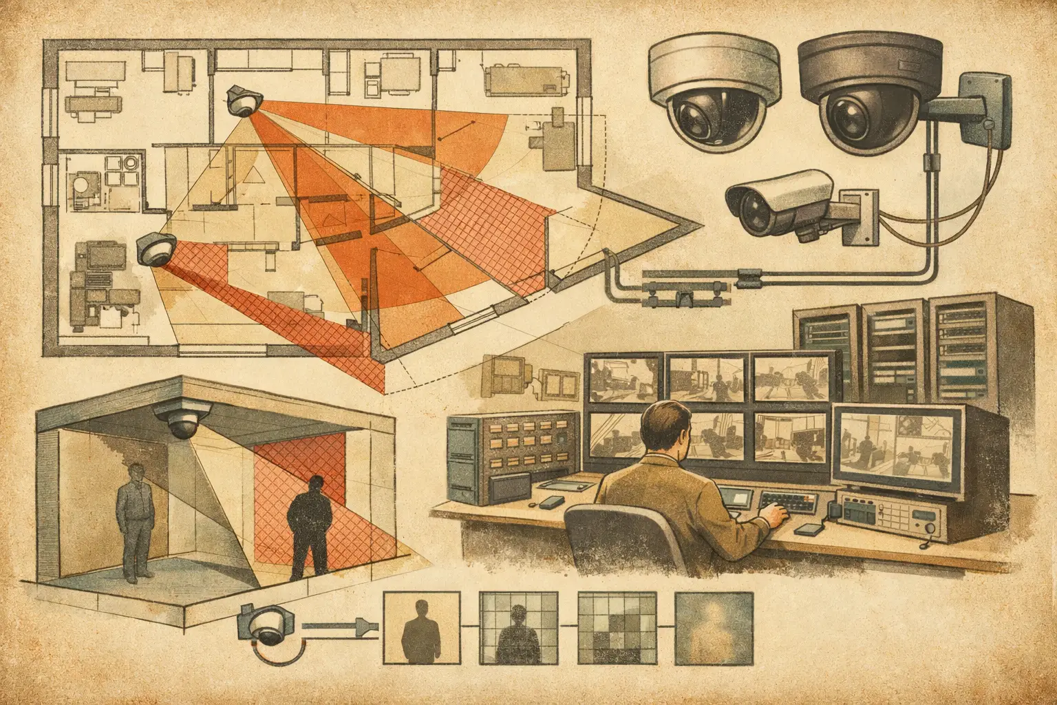
A camera icon on a floor plan is not evidence of coverage. To understand how to find CCTV blind spots, security teams need to test the actual field of view against geometry, optical performance, operational objectives, and likely changes in the environment. A wide coverage cone may show an area visually while still failing to provide enough pixel density to identify a person, read a relevant detail, or support the stated security objective.
Blind-spot review is therefore an engineering task, not a drawing exercise. The goal is to produce a traceable view of what each camera can see, what it cannot see, and where another measure - such as revised positioning, a different lens, improved lighting, or an additional camera - may be required.
Start With a Calibrated, Current Drawing
A blind-spot analysis is only as reliable as the plan beneath it. Import the latest architectural or site drawing, then calibrate its scale using a known dimension. A scale error changes calculated distances, field-of-view widths, pixel density, and the apparent relationship between cameras and obstructions.
Review walls, doors, glazing, columns, racking, gates, counters, landscaping, and other physical geometry before placing cameras. On an indoor plan, a door shown open versus closed can materially alter a corridor view. On an outdoor site, a boundary wall may hide an approach route even when a camera appears to cover the general area.
Use the design stage to distinguish verified geometry from assumptions. AI-assisted wall detection or imported CAD linework can speed up setup, but it still requires review. Incomplete walls, incorrect room boundaries, and missing height information can create false confidence in a coverage drawing.
Define What Coverage Must Achieve
A blind spot is not always an unobserved patch of floor. It can also be an area where image detail falls below the level needed for the task. Before reviewing camera locations, define the required observation outcome for each zone.
DORI provides a useful framework for this decision: detection, observation, recognition, and identification require progressively more image detail. Pixel density, commonly expressed as pixels per meter or PPM, converts that requirement into a measurable design condition. A loading yard may only need detection across its general perimeter, while a pedestrian entrance may require recognition or identification at a controlled point.
This distinction prevents a common design error: treating all visible areas as equally covered. A camera may detect movement at the far end of a parking area but not provide sufficient PPM for identification. That is an operational limitation, even if the field-of-view overlay reaches the area.
Assign Requirements by Zone, Not by Camera
Define requirements around risk locations and operational activities: entrances, reception desks, emergency exits, cash handling points, server rooms, vehicle gates, pedestrian routes, loading bays, and perimeter approaches. Then assess which cameras contribute to each requirement.
This approach also identifies coverage overlap that is purposeful versus overlap that consumes capacity without improving the security outcome. Two cameras viewing the same doorway from different angles may reduce occlusion and provide resilience. Two cameras duplicating a low-risk open area may leave a more critical route underserved.
Model the Real Field of View
Camera selection and positioning should be based on technical parameters, not a generic cone shape. Set the resolution, sensor size, focal length, mounting height, direction, and tilt for each proposed camera. These inputs determine the field of view and the pixel density delivered at different distances from the camera.
A short focal length can cover a broad scene, but its PPM falls as the scene width and distance increase. A longer focal length narrows the view and can improve detail at a target point, but it may introduce gaps at the sides or immediately below the camera. Neither configuration is inherently better. The correct choice depends on the target distance, required DORI level, and physical constraints.
Mounting height and tilt deserve the same scrutiny. A high-mounted camera can reduce interference and widen general visibility, but it may create poor facial angles, hide areas close to the wall, or increase the effect of shelves and canopies. A lower position can improve target detail but may be more vulnerable to tampering or obstruction. Review the coverage in plan view and, where available, account for elevation and likely sightline interference.
Test for Occlusion, Not Just Coverage Gaps
The most consequential blind spots often result from occlusion. A wall, column, parked vehicle, storage rack, sign, tree canopy, or open door can block a camera's line of sight even though the target area appears inside its theoretical field of view.
Start with fixed obstructions. Trace the line from the camera to critical points such as a doorway threshold, the corner of a corridor, a gate control point, or the end of a pedestrian path. If a wall intersects that line, the location is not covered. Do not assume a camera mounted near a corner can see around the corner.
Then consider variable obstructions. Warehouses change with pallet heights and seasonal storage. Retail layouts change with displays. Delivery areas fill with trucks, containers, and trailers. Outdoor views can be affected by landscaping growth, parked vehicles, sunshades, and temporary construction works. These factors may not be fully represented in a base plan, so record them as assumptions for site verification.
Review the Near Field
The area immediately beneath or close to a camera is easy to overlook. Depending on mounting height, tilt, lens selection, and the camera housing position, a camera may have a significant near-field blind spot. This matters at doors, gates, building corners, and access-controlled barriers, where the critical action happens close to the mounting location.
Check the field-of-view boundary at the actual target plane, not only at the far edge of the drawing. A camera that sees a corridor's distant end may miss the first several feet of the corridor or the space directly beside a doorway.
Use Overlap Deliberately
Coverage overlap is not a failure by default. It is often necessary where a single view is vulnerable to occlusion, poor angle, glare, or temporary blockage. For example, an entrance camera facing outward may capture approaching subjects, while a second camera from inside the lobby records the direction of travel and face angle after entry.
The trade-off is cost, network capacity, recording storage, installation complexity, and review workload. Add overlap where it supports a documented purpose, such as reducing a known occlusion point or supporting a higher DORI requirement. Avoid treating overlap as a substitute for analysis of the actual blind area.
Network topology should also be considered before the design is finalized. Additional cameras can affect switch ports, PoE budgets, uplink capacity, cable pathways, and recording estimates. A blind-spot correction that cannot be supported by the planned network is not yet a deployable solution.
Conduct a Structured Blind-Spot Review
A practical review works best when it follows a repeatable sequence rather than informal visual inspection. For each critical zone, verify the design against these questions:
- Is the plan scale calibrated and is the physical geometry current?
- Does the camera field of view reach the intended target area without wall or object occlusion?
- Does the calculated PPM meet the required DORI level at the target distance?
- Is the near field below or beside the camera covered where needed?
- Could doors, vehicles, racking, landscaping, or normal site activity block the view?
- Is overlap intentional, and does it improve the operational result?
- Can the network and recording design support the revised camera count and configuration?
Document findings camera by camera and zone by zone. A marked plan should show camera direction, coverage boundaries, blind areas, relevant PPM or DORI outputs, and assumptions requiring confirmation. This creates a clearer review record for consultants, installers, architects, project owners, and ICT teams than a set of untested camera symbols.
Validate Calculations on Site
Calculated results are a disciplined basis for design, but they are not a substitute for installation-stage verification. Site conditions can differ from drawings: ceiling heights vary, mounting positions shift around services, finishes create reflections, and a proposed camera location may be inaccessible or visually unacceptable.
During commissioning, confirm the installed camera height, focal length or varifocal setting, direction, tilt, scene framing, and image quality at the intended target points. Test representative operational conditions, including expected lighting conditions and realistic obstructions where practical. Manufacturer-specific image processing, low-light behavior, compression settings, and recorder configuration can affect actual performance beyond geometric calculations.
CCTV Design Tool Online can support this workflow by combining calibrated plans, physical geometry, camera parameters, field-of-view visualization, DORI and pixel-density review, and structured reporting in one design workspace. The output still requires professional review against the project brief, site conditions, manufacturer documentation, and any applicable local requirements.
A well-documented blind-spot review does more than add cameras. It helps the project team explain why each camera is positioned where it is, what performance is expected at each critical location, and which assumptions must be checked before handover.