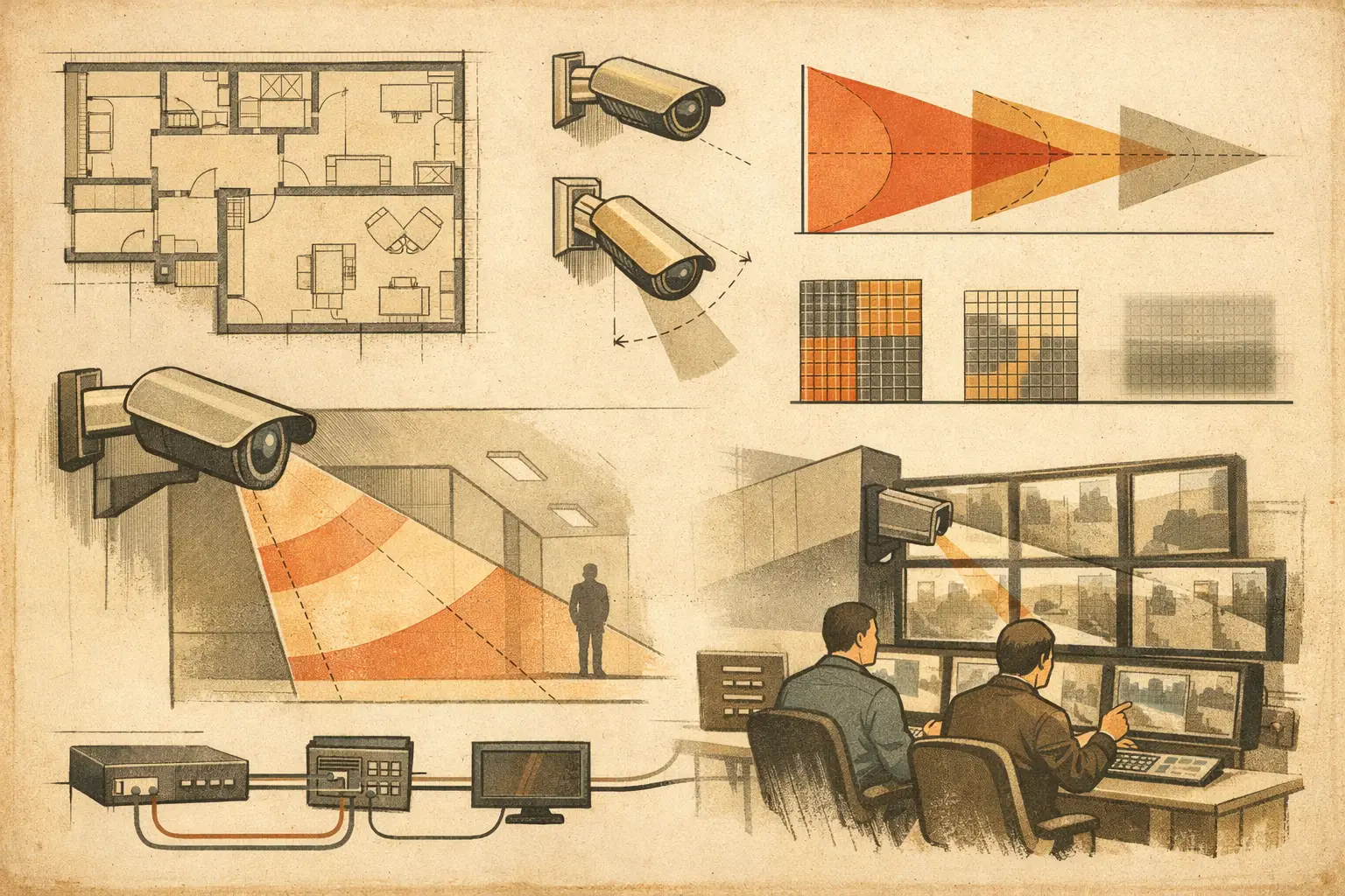
A camera can show a wide area and still fail the operational requirement. The usual cause is not the camera model - it is the relationship between mounting height, target distance, lens geometry, and tilt. A security camera tilt angle calculator turns those inputs into a repeatable starting point for aiming cameras before installation, rather than relying on a coverage cone drawn by eye.
For a consultant, installer, or reviewer, tilt is not a cosmetic setting. It changes where the optical axis lands, how much of the image is occupied by the ground plane, the useful distance to the near and far edges of coverage, and the pixel density available at the point of interest. It also affects whether walls, canopies, racking, vehicles, and other physical geometry create occlusions that a simple 2D drawing may miss.
What a security camera tilt angle calculator solves
A tilt calculation answers a defined geometric question: at what downward angle should the camera optical axis point to intersect a target at a specified distance and height?
For a camera mounted at height `Hm`, looking toward a target at height `Ht` and horizontal distance `D`, the basic optical-axis tilt is:
`Tilt angle = arctan((Hm - Ht) / D)`
The angle is measured downward from horizontal. This convention should be confirmed in the design documentation because camera manufacturers and VMS interfaces may display pan and tilt positions differently.
The formula is intentionally simple, but the inputs must be meaningful. Mounting height should be measured from the relevant finished floor or ground level, not from an unverified plan annotation. Target height depends on the task. For a person’s face, the intended point may be above ground level. For a vehicle plate zone, the target height and approach geometry are different. For general situational awareness, the optical axis may be aimed at the center of an area rather than a single identification point.
A calculator produces a calculated angle, not a promise of field performance. Lens distortion, actual mounting position, scene slope, camera housing adjustment limits, and installation tolerances can all change the final view. The result should be verified against the live image during commissioning.
Start with the operational target, not the camera angle
Tilt should follow the surveillance objective. A high-mounted camera looking steeply downward can provide useful overview coverage, but it often reduces facial detail because subjects are viewed from above. A shallow tilt preserves a more horizontal view at distance, but may place the far edge of the scene beyond the required pixel density and can increase glare or backlight exposure.
Define the target point before entering numbers into a calculator. That point may be an entrance threshold, a cashier position, a gate lane, a loading-bay approach, or a pedestrian route. Then determine the required level of detail through the project’s DORI or pixel-density criteria. DORI describes detection, observation, recognition, and identification tasks, while PPM expresses image resolution across a scene width. Neither should be inferred from tilt alone.
A camera aimed correctly at a target can still be incorrectly specified if the focal length, sensor size, resolution, and required PPM do not support the intended task. Conversely, selecting a narrow lens without checking tilt can create a coverage gap near the camera or exclude a critical approach path.
Core inputs for a defensible calculation
The minimum calculation needs mounting height, target height, and horizontal distance. A design review should also record the vertical field of view, horizontal field of view, focal length, sensor size, resolution, mounting surface, and the target PPM or DORI objective.
Vertical field of view is especially relevant because tilt positions the whole image, not only its center. The optical axis might intersect the correct target while the lower edge misses the near approach area or the upper edge extends into irrelevant ceiling, sky, or façade. Camera resolution and aspect ratio also matter because they determine how image pixels are distributed across the scene.
For a varifocal camera, use the focal length actually proposed for the design. A wide-end field of view and a telephoto-end field of view can produce very different near and far coverage limits at the same tilt angle.
Calculate the visible ground range from tilt and vertical field of view
On a level ground plane, tilt can be used with vertical field of view to estimate where the upper and lower image rays intersect the ground. Let `β` be the vertical field of view and `θ` the downward tilt of the optical axis.
The approximate near and far ground distances are:
`Near distance = Hm / tan(θ + β/2)`
`Far distance = Hm / tan(θ - β/2)`
These equations apply only when the relevant rays point below the horizon. If `θ` is less than or equal to half the vertical field of view, the upper ray reaches the horizon or above it, so there is no finite far ground intersection. That may be acceptable for a scene requiring distant context, but it is not a complete ground-coverage calculation.
This is also where a broad field of view creates a trade-off. Increasing vertical field of view can bring the near edge closer to the camera, yet it can make the far edge less controlled and reduce pixel density over the total scene. The correct arrangement depends on the required coverage zone, not on maximizing the visible area.
Worked example
Assume a fixed camera is mounted 12 feet above finished grade. The design intent is to center the optical axis on a point 18 feet away at an estimated target height of 5 feet.
`Tilt = arctan((12 - 5) / 18)`
The calculated downward tilt is approximately 21.3 degrees from horizontal.
Now assume the camera, at its selected focal length, has a vertical field of view of 33 degrees. The lower image ray is approximately 37.8 degrees downward, while the upper image ray is approximately 4.8 degrees downward. On level ground, the image may extend from roughly 15 feet from the camera to approximately 143 feet away.
That apparent range does not mean the camera satisfies a recognition or identification requirement across 143 feet. Pixel density normally falls as the viewed scene width increases with distance. The installer also needs to check whether the far range is blocked by parked vehicles, fencing, landscaping, or a change in grade.
Include geometry that a tilt formula cannot see
A standalone calculator assumes a clean line of sight over a flat plane. Projects rarely offer one. A camera may be mounted under a soffit, beside a structural column, above a doorway, or along a corridor with intervening partitions. The nominal field of view may cross a wall on a floor plan, but a door opening, window, or void may alter what is physically visible.
The design should therefore model walls, openings, and relevant obstructions before treating calculated coverage as usable coverage. Review the camera ray paths in plan and, where mounting heights vary, in elevation or a 3D view. Consider temporary occlusions as well: delivery trucks at a loading dock, queues at an entrance, stacked inventory, and vegetation growth can materially affect the live scene.
Ground slope requires separate care. If grade rises away from the camera, the far edge arrives sooner than the flat-ground equation predicts. If grade falls away, the camera may see farther but with a less useful viewing angle. Stairs, ramps, and multi-level parking areas should be assessed as separate surfaces rather than represented by one average elevation.
Check pixel density at the target plane
The final check is not whether the target appears inside the coverage cone. It is whether the target receives sufficient image detail for the defined task.
At a particular distance, estimate the width of the scene on the target plane using the camera’s horizontal field of view. Divide the horizontal image resolution by that scene width to obtain an approximate PPM value. For angled views of the ground, this should be treated as a design estimate because perspective and lens behavior affect the actual image. The required PPM and DORI interpretation should come from the project brief and applicable client or jurisdictional requirements.
Where the same camera must cover a near doorway and a distant perimeter route, one angle and focal length may not satisfy both tasks. Splitting the requirement between an overview camera and a dedicated detail camera is often more defensible than forcing one broad view to perform every function.
Use the calculation in a coordinated design workflow
A useful workflow begins by importing and scale-calibrating the drawing. Place the camera at its realistic mounting location, including the selected mounting height. Set sensor size, resolution, focal length, direction, and calculated tilt. Then review the resulting field of view against walls, openings, target zones, coverage overlap, blind spots, and expected obstructions.
CCTV Design Tool Online supports this type of persistent design workflow by connecting floor-plan geometry, camera parameters, field-of-view visualization, pixel-density analysis, and technical reporting. The calculation remains traceable because reviewers can see the assumptions behind the angle rather than receiving an unexplained camera symbol on a drawing.
Record the intended target distance, target height, calculated tilt, selected focal length, and required operational outcome in the camera schedule or report. This gives the installer a clear starting point and gives the project team a basis for reviewing changes caused by site conditions.
A well-calculated tilt angle is best treated as an engineering instruction to verify, not a number to defend after the camera is installed. Aim for the defined target, confirm the live field of view and pixel density, then document any field adjustment so the as-built system remains understandable long after commissioning.