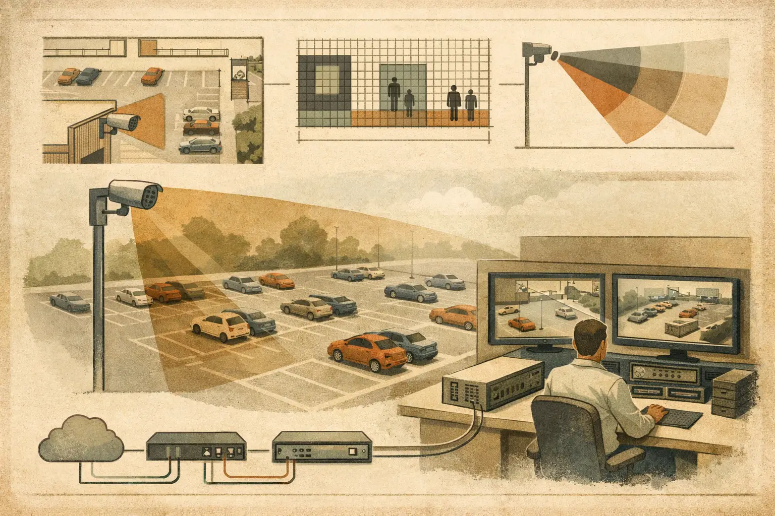
A parking lot camera example is most useful when it starts with a real operational question, not a camera count. Can security staff identify a person walking between vehicles? Can they recognize a vehicle entering through a gate? Can they review a collision near accessible parking or confirm activity at a loading-area door? Each question requires different image detail, viewing geometry, and coverage priorities.
Consider a mid-size office parking lot with 72 spaces, two vehicle entrances, a pedestrian route to the main building, and a service gate at the rear. The site is approximately 180 feet by 115 feet, with light poles around the perimeter and a building facade along one side. This is a practical design scenario because it combines wide-area observation, vehicle movement, pedestrian safety, and several predictable sources of occlusion.
Start the Parking Lot Camera Example With Requirements
Before placing cameras, separate the lot into operational zones. In this example, the entrance and exit need vehicle observation. The pedestrian route needs usable identification coverage. The central parking bays need general observation and post-incident review. The service gate needs a tighter view because vehicles, deliveries, and people may use the same constrained access point.
These are not interchangeable objectives. A wide-angle camera mounted high on a light pole may provide strong situational awareness across several rows of spaces, while delivering insufficient pixel density at the far end for reliable identification. Conversely, a narrow field of view aimed at an entrance can provide greater detail but cannot replace broad-area observation.
Document the required result for every zone using a defined DORI or project-specific PPM target. DORI expresses four practical levels of detail: detection, observation, recognition, and identification. PPM, or pixels per meter, provides a measurable image-detail reference across a scene. The required value should come from the project brief, risk assessment, or applicable client criteria rather than an assumed universal number.
Build a Scaled Site Model
Import the parking-lot drawing and calibrate its scale using a known dimension, such as the length of a marked parking bay, a surveyed boundary, or a building facade. Scale calibration matters because an error in drawing scale affects every subsequent calculation, including field of view, coverage distance, pixel density, cable lengths, and storage estimates.
Next, model physical geometry that affects lines of sight. In an outdoor lot, this usually includes the building edge, boundary walls, gates, raised planters, canopies, equipment enclosures, and substantial signs. A painted parking line is not an occlusion. A delivery truck, SUV, landscaping, or a solid gate can be.
Temporary obstructions deserve consideration as well. The view from a 20-foot pole-mounted camera may be clear when the lot is empty but blocked at ground level by parked vehicles. This does not automatically make the camera position unsuitable. It means the intended task must be realistic. A camera designed for general observation can tolerate more intermittent obstruction than one expected to identify a person between every row of parked cars.
Position Cameras by Task, Not by Symmetry
For this site, begin with an overview camera at each front corner of the parking area. Mounting these cameras on existing poles at approximately 18 to 22 feet can provide useful cross-lot views while reducing the likelihood of casual tampering. Direct each camera diagonally across the lot rather than straight down a parking aisle. Diagonal views make it easier to observe movement between rows and reduce the tunnel effect created by long, narrow aisles.
A third overview camera can cover the rear bays and service approach. Its field of view should overlap the two front cameras at key circulation points, such as the main driving aisle and pedestrian crossing. Coverage overlap is valuable where an incident may be partly concealed by a parked vehicle, but it should be intentional. Adding overlap everywhere can create unnecessary camera count, bandwidth, and review workload.
Use dedicated cameras for the two vehicle entrances. These should be aimed at the controlled movement zone, not simply placed near the gate. Camera direction, mounting height, focal length, sensor size, and tilt should be selected to achieve the required pixel density where a vehicle or person is expected to pass.
If the brief requires license plate capture, that is a separate application from general entrance observation. Plate readability depends on more than resolution. Vehicle speed, angle, lighting, shutter settings, illumination, compression, and local conditions all affect performance. A calculated field of view can support design review, but actual performance should be verified during commissioning under representative day and night conditions.
Select Optics From the Required Coverage Width
Assume the main entrance lane is 16 feet wide and the camera is mounted 25 feet from the intended capture point. A varifocal camera may be appropriate because it allows the designer to set a narrower field of view around the lane rather than wasting pixels on adjacent landscaping or roadway.
The central lot is different. A wider lens may cover three rows of parking and the driving aisle, but the farther spaces will have lower pixel density. Review the PPM map or DORI result across the whole field of view, not only at the center. The edges and far boundary are often where a visually convincing coverage cone hides weak detail.
Mounting height and tilt are linked. Raising a camera increases the area visible behind parked vehicles and can improve overview coverage, but it also steepens the viewing angle. Faces may become less useful for identification, and the image can devote more pixels to pavement than to the subject. Lowering the camera can improve facial viewing angle in a targeted zone, while increasing vulnerability and susceptibility to vehicle occlusion.
There is no single correct height for every camera in a parking lot. Use the height that supports the assigned task, then validate the projected coverage against the modeled environment.
Check Blind Spots and Night Conditions
In the example layout, the most likely blind spots are beside the building entrance, immediately behind the service gate, and between tall vehicles in the inner rows. The building entrance may need its own dedicated camera because a wide parking-lot view is rarely an adequate substitute for a doorway view.
The service gate also benefits from two perspectives when risk justifies it: one camera observing the approach and another viewing activity within the gate line. This arrangement can reduce occlusion caused by an opening gate or a stopped delivery vehicle. Whether the second camera is necessary depends on the operational consequence of a missed event and the available infrastructure.
Night performance must be reviewed as part of the design rather than left to the camera specification alone. Assess existing pole lighting, headlight glare at entrances, reflective pavement markings, vehicle shadows, and light spill from the building. A camera may show an acceptable calculated field of view while still producing poor usable imagery when strong headlights point directly toward it.
Where lighting changes across the site, record those conditions in the design notes. Manufacturer-specific low-light performance, wide dynamic range behavior, and infrared range should be checked against verified datasheets and evaluated during site testing. Design calculations describe geometry and expected pixel density; they do not replace commissioning tests.
Coordinate Power, Network, and Documentation
A parking-lot layout is also an infrastructure design. Map each camera to the nearest suitable communications cabinet, field switch, or building entry point. Confirm whether pole locations have power, whether fiber or copper pathways are feasible, and where surge protection, weather-rated enclosures, and grounding requirements may apply. These details are project- and jurisdiction-specific and should be reviewed by qualified electrical and network professionals.
For the example site, grouping the three overview cameras on a field switch near the front lot may reduce cable routes, while the rear service-gate camera may require a separate pathway back to the building. Network topology should account for cable distance, PoE budget, uplink capacity, resilience requirements, and the selected camera stream settings. A high-resolution camera with multiple streams can affect bandwidth and storage far more than a simple symbol on a plan suggests.
The deliverable should show camera IDs, mounting locations, heights, directions, fields of view, focal-length settings or ranges, DORI or PPM results, blind-spot notes, and network connection paths. Include assumptions clearly, especially where a site survey, final lighting test, or manufacturer datasheet review is still required.
CCTV Design Tool Online can support this workflow in one design workspace by combining calibrated drawings, modeled obstructions, camera parameters, field-of-view visualization, coverage analysis, network planning, and structured reporting. The result remains an engineering deliverable that should be reviewed against the actual site, project brief, and installation constraints.
A useful parking-lot design is not the one with the most camera icons. It is the one where every camera has a stated purpose, a measurable coverage expectation, and a documented reason for its placement.